Electrical connection v1 weathertight, V2 explosion proof, hermetically sealed – SOR Dual Hi-Lo Weatherproof Pressure Switch User Manual
Page 3
Form 248 (04.13) ©SOR Inc.
3/4
Electrical Connection
V1 WEATHERTIGHT
Common
Normally Open
Normally Closed
SPDT: Screw terminal block with marked insulation. Left and right positions.
No. 1 (Left side)
C1
NO1
NC1
No. 2 (Right side)
C2
NO2
NC2
2-SPDT (DPDT): Left and right positions
Nos. 1 & 2 (Left side)
C1
NO1
NC1
C2
NO2
NC2
Nos. 3 & 4 (Right side)
C3
NO3
NC3
C4
NO4
NC4
Ensure that wiring conforms to all applicable local and national electrical codes and install
unit(s) according to relevant national and local safety codes.
Units in hazardous locations— Prior to removal from service, make sure
that the work area is declassifi ed. Failure to do so could result in severe
personal injury or substantial property damage.
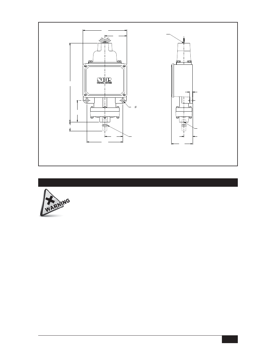
Linear = mm/inches
Drawing 0090281
69.5
2.74
139.9
5.51
57.2
2.25
114.3
4.50
2X
MOUNTING
HOLES
7.1
0.28
9.5
0.38
27.8
1.09
A
*68.6
2.70
*251.2
9.89
69.9
2.75
1/4 OR 1/2 NPTM
PROCESS CONNECTION
OPTIONAL
1/4 OR 1/2 NPTF
PROCESS
CONNECTION
ELECTRICAL
CONNECTION
3/4 NPTF STD
1/2 NPTF OPT
FACTORY SEALED
WIRE LEADS
V2 EXPLOSION PROOF, HERMETICALLY SEALED
Dimensions are for reference only. Contact the factory for
certified drawings for a particular model number.