Max) = v, 8v 20ma – SOR 805QS Pressure Switch-Transmitter User Manual
Page 3
Form 1547 (10.13) ©SOR Inc.
3/8
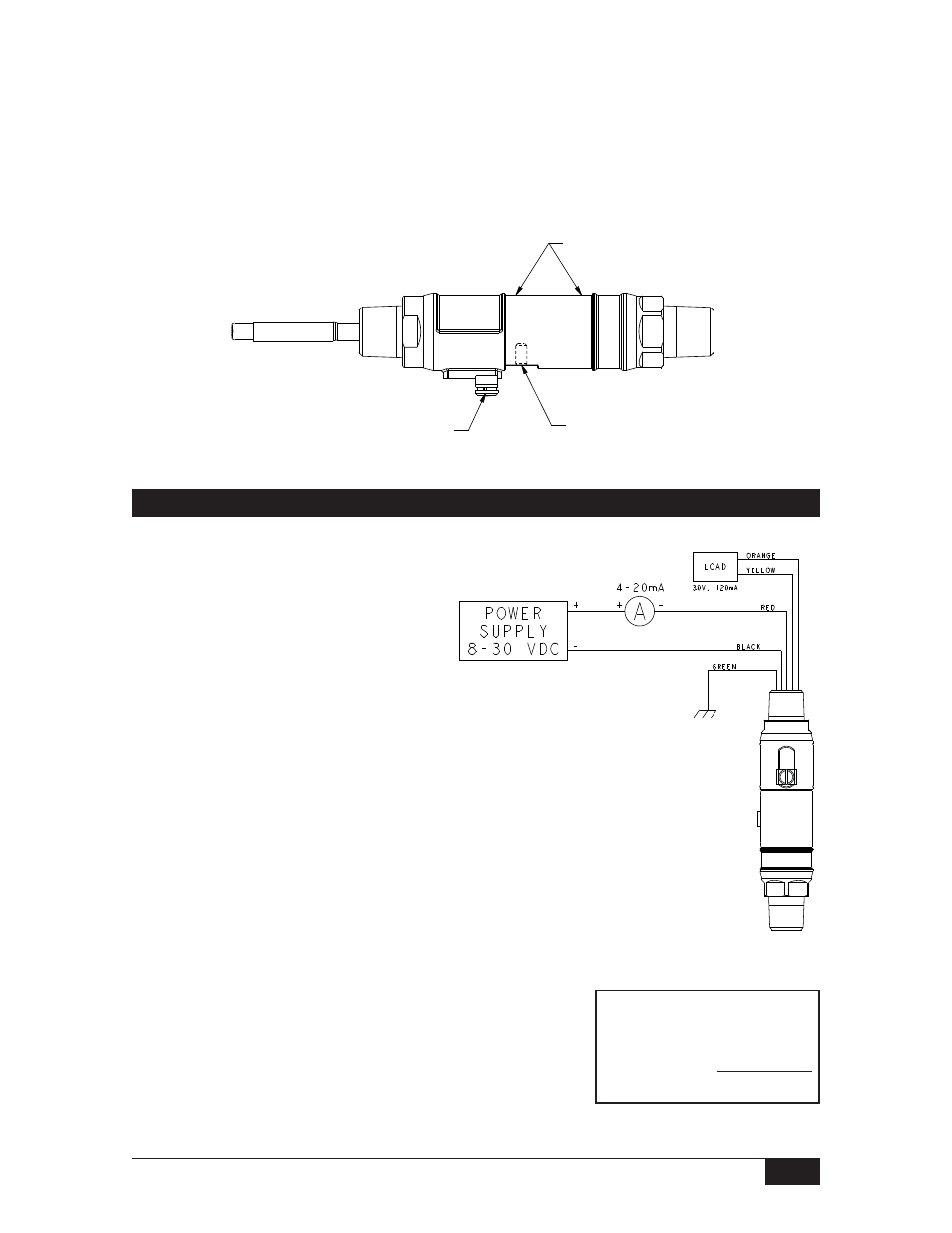
Electrical Termination - 805QS-C
Drawing 0190323
Formula for determining
maximum loop resistance
R
L
(MAX) = V
Supply
- 8V
20mA
NOTE: An external ground screw is included for additional
earth ground connection.
72” flying leads are provided for
connection to a terminal strip
within a cabinet or a splice within
an outlet box:
Red (+)
Loop Voltage: 8 to 30 VDC
Black (–)
Output: 4 to 20 mA
Orange Switch
Contacts
Yellow
Normally-Open Solid-State Relay
Blue
(Used for 805QS-V Models Only)
Green Earth Ground
White Calibration
(Requires SOR Calibration Kit)
Brown
Not Used (trimmed at factory)
Bare
Drain Wire - Connected to
Earth Ground (trimmed at factory)
}
}
Horizontal Installation
The following figure depicts the proper horizontal installation profile; with the external
ground provision and set screw (annunciation path) oriented downward.
The nameplate (tag) should not cover the set screw. Align the nameplate slot with the
set screw; i.e., the set screw should be visible in the nameplate slot.
SET SCREW
ANNUNCIATION PATH
NAMEPLATE AREA
EXTERNAL GROUND
PROVISION