Rear panel, User manual and installer guide, Visionpro hdp – Lumagen VisionProHDP User Manual
Page 10: The connections are, Provides analog rgb or component video output, Provides digital (dvi-d) video output, Menu as, The separate composite sync types are specified as, Or for rgbcvs as, Channel as blue and the p
VisionPro HDP
™
User Manual and Installer Guide
© 2004-2006 Lumagen®, Inc.
7
Rev 1.1
Rear Panel
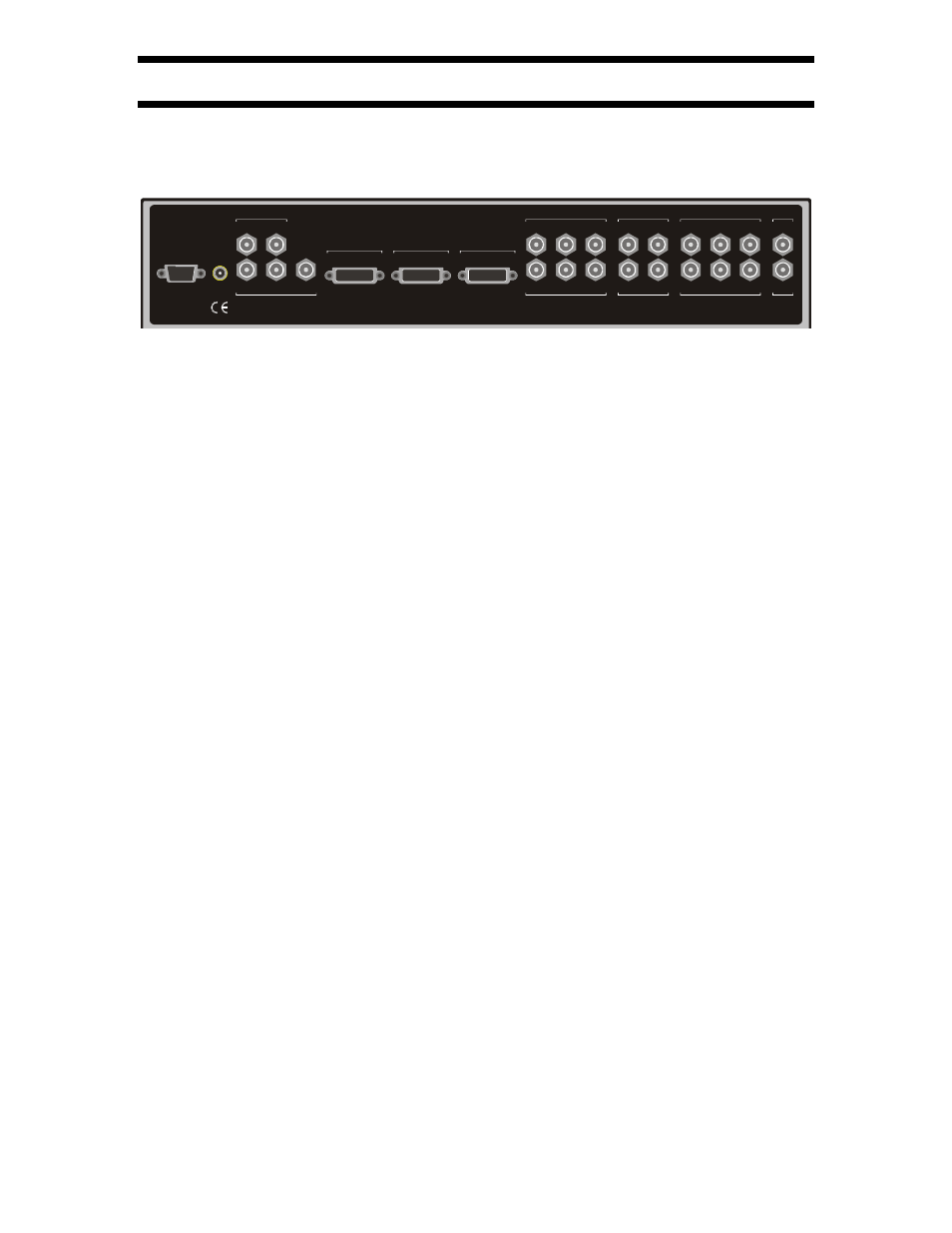
All connections are made on the rear panel, which is shown below.
INPUT 5 - SD ONLY
C
Y
Y
INPUT 6 - SD ONLY
C
OUTPUT
G/ Y
R/ P
R
B/ P
B
HCSYNC
OUTPUT
VSYNC
Manufactured in U.S.A.
POWER
INPUT 3 - SD/ ED/ HD
Y
P
R
P
B
Y
INPUT 4 - SD/ ED/ HD
P
R
P
B
INPUT 9
SDI
INPUT 0
SDI
INPUT 7 - SD ONLY
Y
C/ P
R
P
B
Y
INPUT 8 - SD ONLY
C/ P
R
P
B
No user serviceable parts
inside. Refer servicing to
factory authorized agent.
DVI-D
INPUT 1
DVI-D
OUTPUT
DVI-D
INPUT 2
This device complies with part 15 of the FCC Rules, Canadian ICES-003, and CISPR 22. Operation is
subject to the following two conditions: (1) This device may not cause harmful interference, and (2) this
device must accept any interference received, including interference that may cause undesired operation.
The user must read and accept license agreement before using this product.
5V DC
RS-232 CONTROL
The connections are:
•
RS-232
: Connect the supplied external 5 Volt DC, at 5 amp, power supply.
•
POWER
: Connect to the external supplied 5 Volt DC power supply.
•
Analog Video output
: Provides analog RGB or component video output.
•
DVI-I Video output
: Provides digital (DVI-D) video output.
•
INPUT 1
to
INPUT 0
: Standard input connections.
Input 1 and 2: DVI-D with HDCP support
Input 3 and 4: SD/HD Component, or RGB
Input 5 and 6: SVideo or Composite (selectable)
Input 7 and 8: SD Component, SVideo or Composite (selectable)
Input 9 and 0: SDI (Serial-Digital-Interface)
The RS232 serial port allows the use of an external home theater RS232 controller. This
is the same as a PC DB9 serial port, except no “flow-control” is used. For updates,
connect to the PC using a DB9-F to DB9-F null-modem cable.
Analog output supports RGBHV, RGsB, RGBS or component, using BNC connectors.
For component output the Y channel is connected to green, the PR channel to red and the
PB channel to blue. Digital output uses a DVI-D connection, which can also drive a
HDMI display using an adaptor cable.
It is possible to connect two RGsB (sync-on-green), two RGBS (TTL level sync), or two
RGBcvS (video level sync) video sources, or a combination, using one or both of the
component/RGB inputs For RGsB, the input is specified as
RGsB
in the input
TYPE
menu
as (
MENU
→
IN
→
TYPE
→
RGsB
). The separate composite sync types are specified as
RGBS
(
MENU
→
IN
→
TYPE
→
RGBS
) or for RGBcvS as
SCART
(
MENU
→
IN
→
TYPE
→
SCART
). For all RGB formats, the Y channel is used as Green, the P
B
channel as Blue and
the P
R
channel as Red. For the separate composite sync types, input 5 is used for sync
input for input 3, and input 6 is used for sync input for input 4. Up to two RGBHV (TTL
level sync) inputs can be specified (
MENU
→
IN
→
TYPE
→
RGBHV
) using component input
3 and input 5 together or using component input 4 and input 6 together. In this case,
composite or horizontal sync uses the Y connection of input 5, or 6, and the vertical sync
when needed uses the C connection of input 5, or 6.