Fly high with hitec – HITEC Sky Scout (2GO) User Manual
Page 19
19
Fly high with Hitec
Section Seven: Repair and Maintenance of Your Model
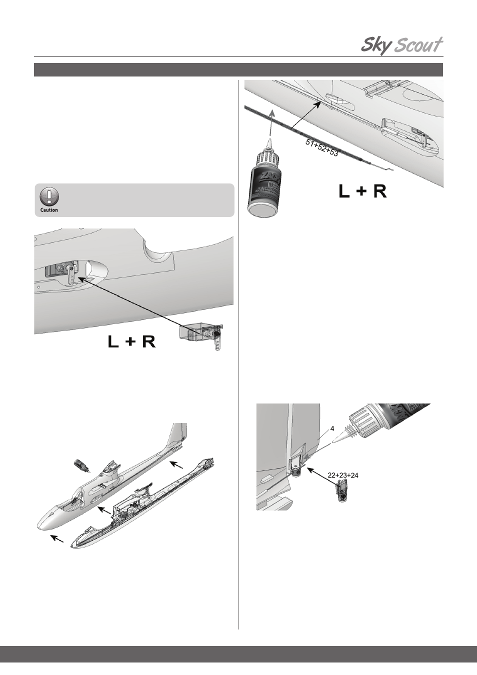
11. Preparing the servos for installation
Before installing the servos, set all of them to neutral (center) from the
transmitter: this is accomplished by connecting the servo to a receiver,
switching the system on, and centering the stick at the transmitter; check
that the transmitter trims are also at the neutral position.
Locate the “double-ended” servo output levers with three holes per side,
fit them on the servo output shafts at right-angles to the long side of the
servo cases. If you find that the output arm is not accurately at right-an-
gles to the case when the servo is at neutral, rotate the lever through 180°
and try again; the output shaft features an odd number of splines, and
reversing the output device will get you “closer to the target”.
Install the elevator and rudder servos as a mirror-image pair. You will do
the same with the aileron servos, if you choose to install them.
12. Installing the servos in the fuselage
Fit the servos in the servo mounts
43, with the output arms facing down,
and the output shafts towards the nose. Trim the unused output arm if
needed to prevent interference with the fuselage.
13. Joining the fuselage shells
Spray the joint surfaces of one fuselage shell with activator, apply medi-
um-viscosity CA glue to the joint surfaces of the other shell, then quickly
join the two shells, making sure to align the parts accurately.
14. Installing the snakes
Slip the pre-formed steel pushrods
51 for the elevator and rudder into the
inner tubes
52 (550 mm), and fit these into the prepared outer sleeves 53,
which are
523 mm long.
Connect the pre-formed end of the pushrod to the second hole from the
outside of the servo output arm. Glue the snake outers in the appropriate
channels, running CA glue right along the channel.
16. Attaching the horns to the rudder
Spray activator on the joint surface (the underside) of the horns. Apply CA
Glue to the horn recess in the rudder. Leave the fluid to air-dry for a few
seconds, then press the horn into its recess. Slip the steel pushrod for the
rudder linkage through the hole in the swivel barrel 23. Check once more
that the servos are at center before tightening the Allen-head grub screws
24. We recommend that you apply a drop of medium-strength thread-lock
fluid to each grub screw to prevent them working loose over time.
15. Preparing the control surface horns
Fit the allen-head grubscrews
24 in the swivel barrels 23: two for elevator
and rudder, four if working ailerons are to be fitted. Engage the prepared
swivel barrels in the “Twin”
horns 22.
Avoid moving the servo output levers by hand, as this
can easily ruin the gears!