Fly high with hitec – HITEC Sky Scout (2GO) User Manual
Page 13
13
Fly high with Hitec
Section Six: Adding the Optional Ailerons to Your Model
The Sky Scout is designed for success in a “3-channel” configuration using rudder, elevator and throttle control. This basic configuration is well suited to
beginners and relaxing flying. More experienced pilots may prefer to increase the performance of their Sky Scout by adding the optional aileron controls.
The necessary hardware to ailerons is included with your Sky Scout package. In addition to these parts you will need two additional servos and two
servo extensions. Hitec Recommends using HS-55L (long servo lead version & two 57345S, 12 inch extensions. The following describes the installation
process of adding ailerons. The information below is for installing ailerons in a new fuselage. To install ailerons in an assembled model you only need to
do parts 3 and 4.
2
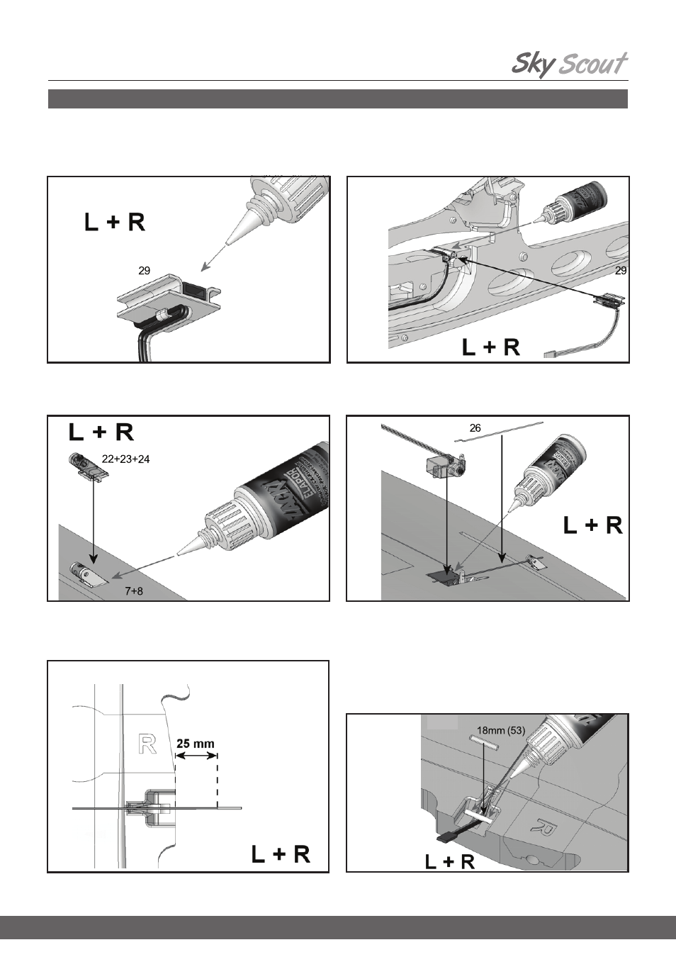
Attaching the (optional) aileron horns
Assemble the “Twin” horns
22, and glue them in the recesses in both
ailerons (wing panels
7 + 8) using CA Glue and activator, as described
earlier.
Servo lead length, aileron connections
Draw the servo leads out of the wings 7 + 8 where the wing meets the
fuselage.
Installing the cable sleeves
To avoid kinking the aileron servo leads, glue
18 mm lengths of snake
outer sleeve (3.2mm OD) in the recess where the cables exit the wing.
Installing the aileron servos
Wrap adhesive tape round the servos to prevent glue running inside the case.
Fit the pre-formed aileron pushrods
26 through the second hole from the
outside of the servo output arms. Press the servos and leads into the re-
cesses and channels, and thread the plain end of the pre-formed aileron
pushrods
26 through the swivel barrels mounted on the aileron horns.
Check once more that the servos are at center before tightening the
grubscrews
24 in the swivel barrels. We recommend applying a drop
of medium-strength thread-lock fluid to the grubscrews to prevent them
working loose.
Installing the cable holders
First spray activator on the joint surfaces of the cable holders
29. Allow
the fluid to air-dry, then glue the parts in the appropriate recesses in both
fuselage shells.
Preparing the cable holders (optional: required for ailerons)
Glue the female plug end of a 12” (30mm) servo extension lead to the
cable holder
29, flush with the edge. Push the cable under the lug on the
underside.
1
3
4
5
6