Hanna Instruments PCA 300 Series User Manual
Page 19
19
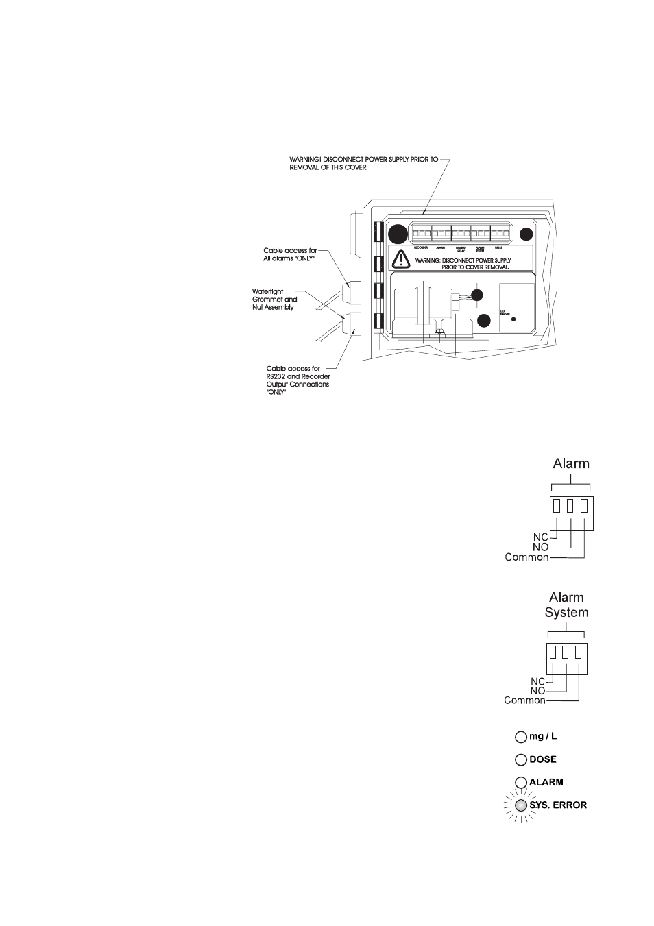
Recorder Output and Relay Access
Hard wiring for alarms and relays can be accomplished
through four watertight connectors on the left of the enclo-
sure, by passing wires through the rubber grommet and
tightening the nut as described earlier.
Refer to the drawing on the right for proper wire connections.
Alarm System
A system alarm feature provides relay acti-
vation to signal need for operator
intervention through an external device, such
as a buzzer, a light or any other electrical
equipment.
Refer to the drawing on the right for proper
wire connections.
The SYS.ERROR LED goes on when a sys-
tem error has occurred. If the situation persists
for more than a few samples, the operator
should notify maintenance personnel for in-
vestigation of the problem. When the meter
is in system error mode, the user can di-
rectly access the diagnostic code that
indicates the source of error (see Error Codes
section at page 49). The analyzer continues
to perform the sampling operations during
an alarm condition.