Maintenance, 2 draining of boiler heating circuit, 3 igniter unit – Glow-worm Flexicom sx User Manual
Page 39: 4 ignition lead, 5 silencer assembly (front), 6 gas valve, 7 flue hood, 8 fan
0020107231_04 - 12/14 - Glow-worm
MAINTENANCE
- 39 -
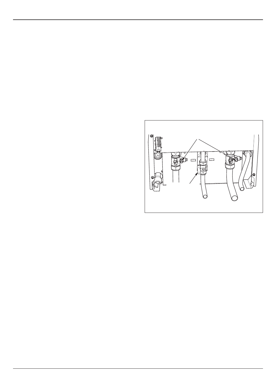
DRAIN POINTS
GAS SERVICE
ISOLATION
VALVE
14 Replacement of Parts
14.1 General
Replacement of parts must be carried out by a
competent
person approved at the time by the Health and Safety
Executive.
Before replacing any parts the boiler should be isolated from
the mains electric supply and the gas should be turned off at the
gas service isolation valve on the boiler, see diagram 14.1.
Ensure that components with electrical connections are
disconnected before removal.
Unless stated otherwise parts are replaced in the reverse order
to removal.
After replacing any parts always test for gas soundness and if
necessary carry out functional test of the controls.
For replacement of parts the front casing of the boiler will
need to be removed. To remove undo the two screws on the
underside of the front casing and lift off.
14.2 Draining of Boiler Heating Circuit
Drain down the Heating Circuit of the boiler only, by closing the
heating flow and return isolating valves on the wall mounting jig.
Attach a length of hose to the drain point and open the drain
valve, see diagram 14.1.
Check for leaks.
14.3 Igniter Unit
For access, refer to section 14.1.
Remove ignition lead and electrical connections then remove
igniter unit by removing two securing screws, see diagram 12.8.
14.4 Ignition Lead
For access, refer to section 14.1.
Pull the spark plug style connector off the spark electrode and
the spade connector connected to the igniter unit, see diagrams
12.5 and 12.8.
14.5 Silencer Assembly (front)
For access, refer to section 14.1.
Pull forwards to remove.
The silencer is a push fit so no tools or fixings are required for
its removal or fitting, see diagram 12.7.
14.6 Gas valve
For access, refer to section 14.1.
Remove the electrical plug from the gas valve.
Undo the tubing nut holding the gas pipe to the gas valve.
Remove the three securing screws, holding the gas valve to the
fan and remove the gas valve, see diagram 12.6.
After re-fitting check the combustion CO2 and adjust if
necessary, refer to section 12 Combustion Check.
After assembly test for gas soundness and purge in accordance
with the current issue of BS6891or in IE, the current edition of
I.S.813 “Domestic Gas Installations”.
Diagram 14.1
13046
14.7 Flue Hood
For access, refer to section 14.1.
Pull the flue hood securing clips away from the flue hood sump
and push flue hood up slightly towards flue hood top, see
diagram 12.4.
To remove swivel flue hood 90° and pull down and out towards
front of boiler, see diagram 12.4.
14.8 Fan
For access, refer to section 14.1.
Remove the gas valve as described in the relevant parts of
section 14.6.
Remove the securing nut holding the fan retaining bracket, lift
front of bracket away from stud and pull forward to release the
fan, see diagram 12.9, check and replace any seals or gaskets
if necessary.