Installation – Glow-worm Flexicom hx User Manual
Page 9
0020107230_04 - 12/14 - Glow-worm
INSTALLATION
- 9 -
3 Boiler Location, Clearances and
Ventilation
3.1 Location
This boiler is not suitable for outdoor installation.
This boiler may be installed in any room, although particular
attention is drawn to the installation of a boiler in a room
containing a bath or shower where reference must be made to
the relevant requirements.
This boiler is suitable for installation in bathroom zones 2 and 3.
In GB this is the current I.E.E. WIRING REGULATIONS and
BUILDING REGULATIONS.
In IE reference should be made to the current edition of I.S.813
“Domestic Gas Installations” and the current ETCI rules.
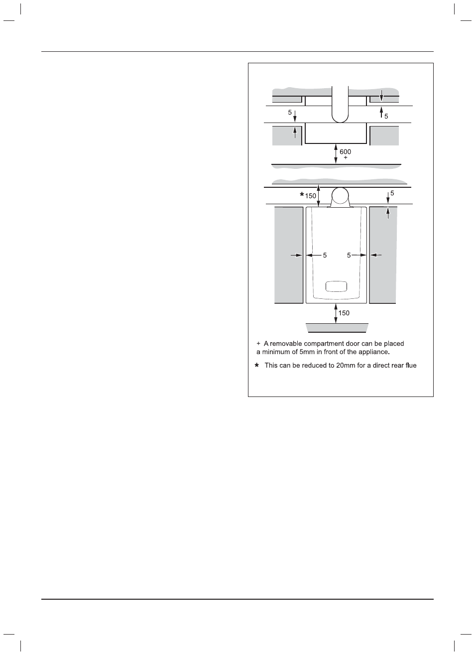
3.2 Clearances
The boiler should be positioned so that at least the minimum
operational and servicing clearances are provided, see diagram
3.1.
Increased clearances would be benefi cial for the installation.
Where external access is not practicable, for fl ue installations
consideration should be given for the space required to insert the
fl ue internally, which may necessitate the clearance to be greater
than those specifi ed in diagram 3.1.
3.3 Timber Frame Buildings
If the boiler is to be installed in a timber frame building it should
be fi tted in accordance with the Institute of Gas Engineers
document IGE/UP/7/1998. If in doubt seek advice from the local
gas undertaking or Glow-worm.
3.4 Combustible Material
The boiler and fl ue are suitable for installation onto and through
combustible materials provided that:-
1) Minimum 5mm clearance is maintained around the
circumference of the fl ue (air intake).
2) The combustible surface and fi xings are suitable for
supporting the load.
3) The minimum clearances from the boiler case are
maintained.
3.5 Room Ventilation
The boiler is room sealed so a permanent air vent is not required.
3.6 Cupboard or Compartment Ventilation
Due to the high effi ciency and hence low casing temperature of
this boiler, cupboard or compartment ventilation is not necessary.
Leave existing air vents.
12792
Diagram 3.1