Installation – Glow-worm Flexicom hx User Manual
Page 20
0020107230_04 - 12/14 - Glow-worm
INSTALLATION
- 20 -
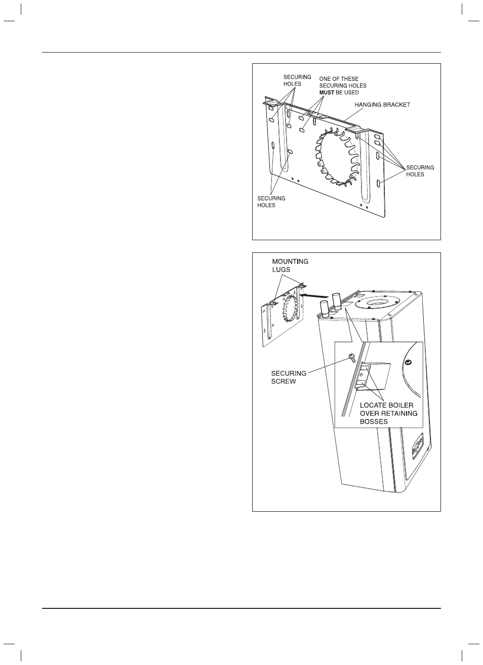
Diagram 7.1
14806
7 Boiler Fixing
7.1 Wall Hanging Bracket
The Wall Hanging Bracket is supplied in the main boiler
packaging.
Reposition the wall template over the fl ue hole and mark the
position of the fi xing holes for the hanging bracket, see diagram
7.1.
NOTE: Due to the varied site conditions we do not supply
fi xings and advise that the installer should supply those which
are suitable.
Drill fi xing holes and insert suitable wall plugs.
Direct Rear Flue only - If external access is not available
the fl ue to be used should be assembled as described in the
separate fl ue instructions and inserted through the hole in the
wall before fi tting the wall hanging bracket.
7.2 Boiler Hanging
IMPORTANT: With regards to the Manual Handling
Operations, 1992 Regulations, the following lift operation
is deemed to be a one man lift, refer to section 16 Manual
Handling.
IMPORTANT: Direct Rear Flue only - The direct rear fl ue
must be fi tted before hanging the boiler, refer to the separate
fl ue instructions, and the rear outlet cover plate should be
removed.
Lifting the boiler into position, lean the top of the boiler slightly
to the wall and position just above the hanging bracket. Lower
the boiler slowly, push back and engage onto the hanging
bracket making sure the boiler is located over the retaining
bosses, secure with screw provided, see diagram 7.2.
Diagram 7.2
14807