Installation – Glow-worm Flexicom hx User Manual
Page 10
0020107230_04 - 12/14 - Glow-worm
INSTALLATION
- 10 -
4 Evacuation of Combustion Gas
4.1 Regulation
Only fl ue accessories supplied by Glow-worm
must be used.
Different fl ue outlet confi gurations can be carried out.
• Consult your supplier for more information about the other
possibilities and associated accessories.
44 mm/m
• Standard
fl ue terminal kits have an in-built fall back to the
boiler to drain the condensate. These can be fi tted level
between the appliance and the termination position. All other
extended fl ues must have a fall of at least 44mm/m
The maximum length of the fl ue outlet is defi ned according to its
type (for example C13).
• Whatever the kind of fl ue system chosen, observe the
minimum distances indicated in the chart below to position
the fl ue terminals.
• To install the fl ue, refer to the separate fl ue instruction
supplied with your appliance.
• Explain these requirements to the user of the appliance.
a
If necessary, you must install terminal
protection.
Caution! The connection between the fl ue
elbow and the fl ue outlet must be sealed.
In GB the minimum acceptable siting dimensions for the
terminal from obstructions, other terminals and ventilation
openings are shown in diagram overleaf.
In IE the minimum distances for fl ue terminal positioning must
be those detailed in I.S.813 “Domestic Gas Installations”.
The terminal must be exposed to the external air, allowing free
passage of air across it at all times.
Being a condensing boiler some pluming may occur from
the fl ue outlet. This should be taken into consideration when
selecting the position for the terminal.
Carports or similar extensions of a roof only, or a roof and one
wall, require special consideration with respect to any openings,
doors, vents or windows under the roof. Care is required
to protect the roof if made of plastic sheeting. If the carport
comprises of a roof and two or more walls, seek advice from the
local gas supply company before installing the boiler.
If the fl ue terminal is positioned near a light
source insects may enter the fl ue system.
Where safe and practical to do so advise the
homeowner to check the fl ue outlet and clear
visible insects from the terminal end.
H* and J* See diagram 4.2. These dimensions comply with
the building regulations, but they may need to be increased to
avoid wall staining and nuisance from pluming depending on
site conditions.
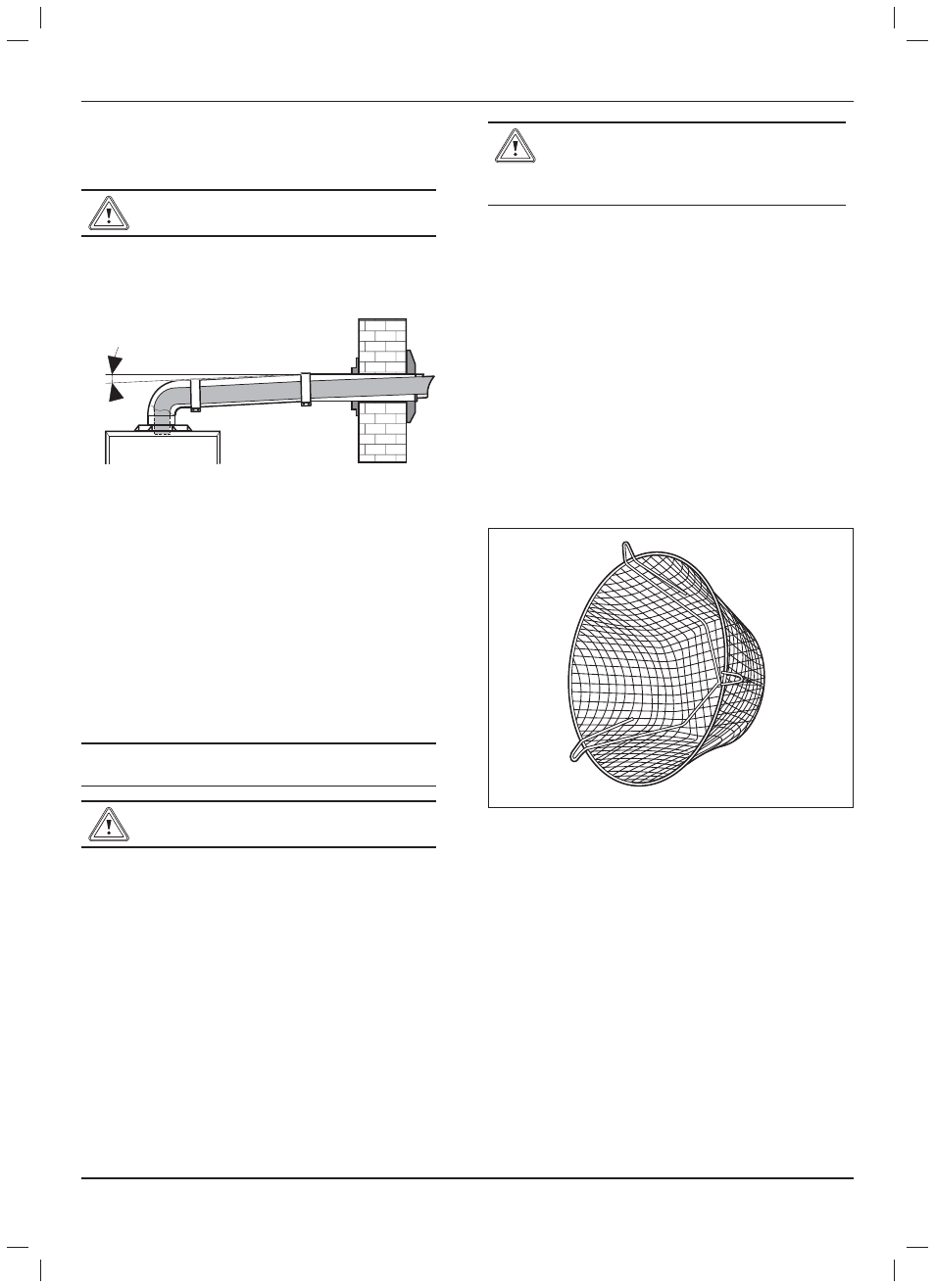
Terminal Guard
A terminal guard is required if persons could come into contact
with the terminal or the terminal could be subject to damage.
If a terminal guard is required, it must be positioned to provide
minimum of 50mm clearance from any part of the terminal and
be central over the terminal.
The guard should be similar to that shown in diagram 4.1.
A suitable guard is manufactured by: -
Tower Flue Components
Morley Rd.
Tonbridge
Kent TN9 1RA.
Size: 280mm x 165mm. Part No: CGDK3
Diagram 4.1
15583