Installation – Glow-worm Flexicom hx User Manual
Page 25
0020107230_04 - 12/14 - Glow-worm
INSTALLATION
- 25 -
13906
Diagram 10.3
10.3 Electrical Cartridge Securing
Close the cartridge and secure with the previously removed
screw.
Push the electrical cartridge into the interface housing on
completion of the wiring, see diagram 10.3.
Secure with the two cartridge retaining screws provided in the
cartridge body.
10.4 Electrical Connections - Testing
Carry out preliminary electrical system checks as below:
1. Test insulation resistance to earth of mains cables.
2. Test the earth continuity and short circuit of cables.
3. Test the polarity of the mains.
NOTE: If you require to test the appliance refer to section 13.
11 Commissioning
IMPORTANT: If the appliance is to be left out of operation after
initial commissioning, ensure all system cleansing and inhibition
has been carried out fully and that power is left on to the
appliance. This is to ensure that there is no risk of fl ammable
gas collecting in the system due to corrosion.
At the time of commissioning, complete all relevant sections of
the Benchmark Checklist located in the inside back pages of
this document.
11.1 Preliminaries - All Systems
DO NOT operate the boiler without water.
The commissioning should be carried out by a competent
person approved at the time by the Health and Safety
Executive in accordance with the current issue of BS6798.
Make sure that the system has been thoroughly fl ushed out with
cold water and that all cleanser, if used, has been removed.
With the gas service isolation valve closed, with no demand
from any external controls and the power supply to the boiler
switched off, test for gas soundness and purge air from the gas
supply.
11.2 Filling the Heating Circuit
With the gas service isolation valve closed and with no demand
from any external controls.
1. Fill the heating system.
Sealed system only - fi ll the system to a pressure of
1.0bar.
2. Vent all air from the system - repeat as
neccessary until the system is full and all the air has
been
vented.
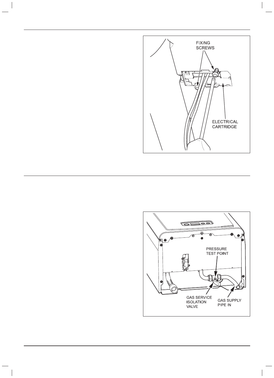
11.3 Gas Supply
The gas valve is factory set for natural gas (G20) and should
need no adjustment. Turn on the gas supply at the isolation
valve, see diagram 11.1. Check the supply pressure at the
pressure test point is 20mbar.
Diagram 11.1
14507