Installation, 8 electrical connections – Glow-worm Climapro2 RF User Manual
Page 10
0020094586_01 - 08/10 - Glow-worm
- 8 -
INSTALLATION
8 electrical connections
The electrical connection of the room thermostat
must be made only by a qualified engineer.
The radio receiver must be connected to the
eBUS connector.
8.1
Main board
1
2
3
30 mm max.
Legend
1 Connector
2 electrical wires
3 Insulation
When connecting electrical cables to a connector of the main
board:
• Maintain a maximum distance of 30 mm between the
connector (1) and the insulation (3).
8.2
Connecting the radio receiver
The location of the EBUS terminal block varies
according to the heating system. It is always
identified by having "BUS" written on it.
• Use the EBUS connection cable provided.
• Cut the EBUS connection cable to the length necessary for
your installation.
Case n°1 - radio receiver on the control box
• Connect the EBUS cable, following the order of operations
from (A) to (F).
A
B
24
V
C
1
2
3
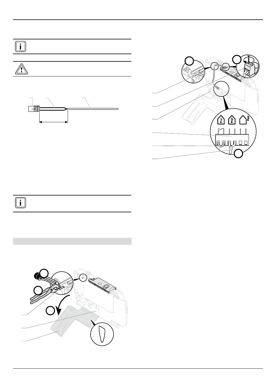
Legend
1 Access for 24 V connection
2 Control box
3 Pre-cut part of control box unit
• Open (A) the access for the 24 V connection (1).
• Cut (B) the pre-cut part (3) of the control box unit (2).
• Remove (C) the pre-cut part of the control box unit (2).
D
RT 24V
T° ext
BUS
BUS
24 V
F
E
1
2
3
6
5
4
Legend
1 ebUS connecting cable
2 Link the connection terminal block on the room thermostat
3 ebUS terminal block for the main board
4 Control box unit
5 Radio receiver connector
6 Pre-cut part of control box unit
• Do not remove the link from the terminal block connecting
the room thermostat to the main board.
• Pass (D) the EBUS cable (1) through the cable passage
created by removing the pre-cut part (6).
• Connect (E and F) the EBUS cable (1) to the radio receiver's
connector (5) and to the EBUS terminal block on the main
board (3). There is no polarity that must be respected.