Assembly instructions, Figure f, Figure h – Elenco SEE AMFM108CK User Manual
Page 9: Figure i, Figure g
-8-
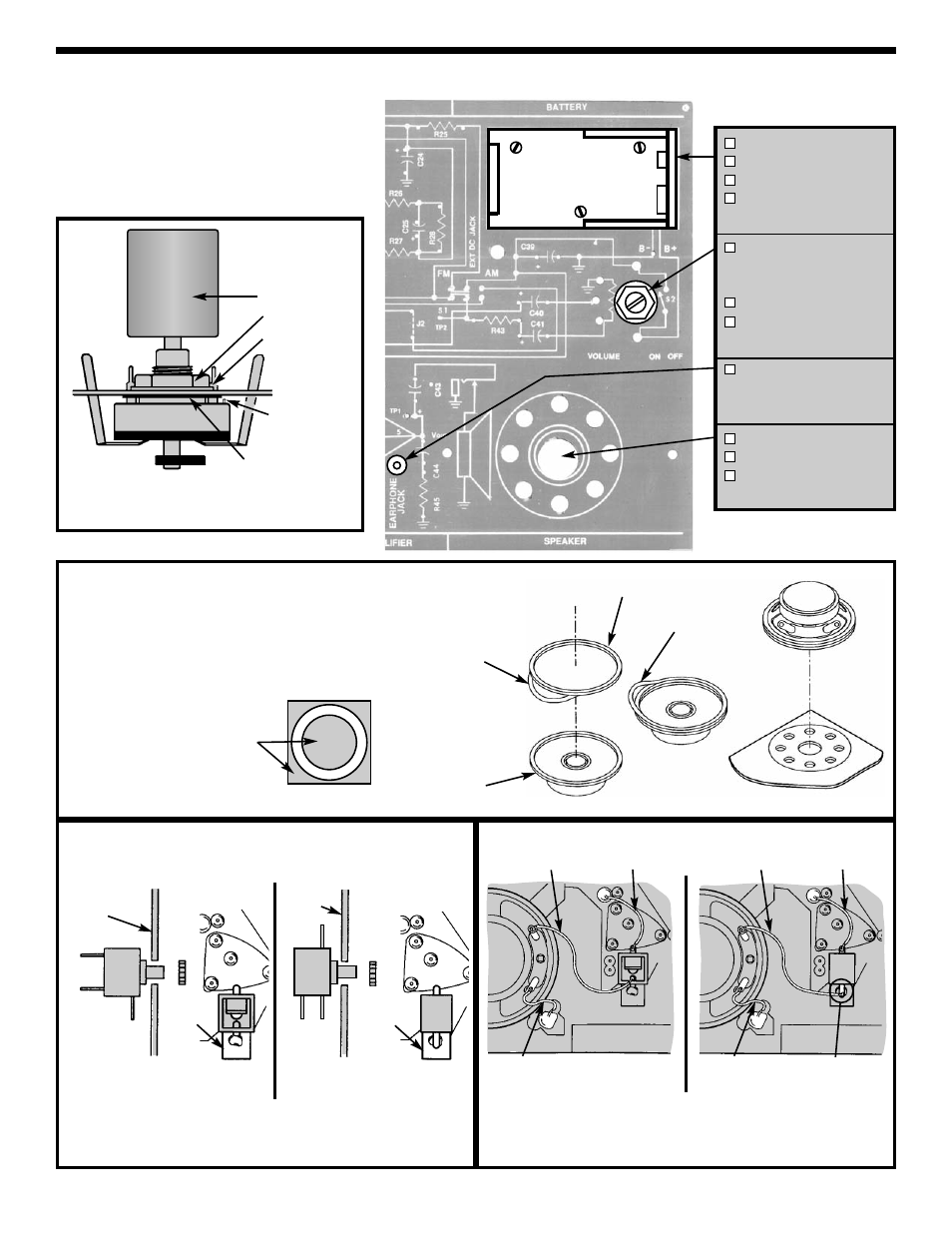
ASSEMBLY INSTRUCTIONS
Figure F
Knob
Nut
Washer
Cut off
locating pin
Solder all 5 tabs to PC board
Plastic Washer
Figure H
Mount the jack with the nut from the foil side of the PC board (terminal #1
on the GND pad of the PC board). Be sure to line up the tab with the pad
on the copper side of the PC board. Solder terminal #1 to the pad of the
PC board.
Part # 622131
1 - GND
2 - Tip
3 - N.C. Tip
1
3
2
Your kit may contain a different type of earphone jack. Before installing
the jack, determine which one you have.
Nut
Figure I
GND
Pad
Cut three wires 1”, 1.5” and 2” and strip 1/4” of insulation off
of both ends. Solder the 3 wires as shown.
*** Save the extra wire for the FM Section. ***
Part # 622130
Part # 622131
Figure G
If the speaker pad has center and outside pieces, then
remove them. Peel the backing off of the speaker pad and
stick the pad onto the speaker. Then stick the speaker
onto the solder side of the PC board as shown.
Pad
Speaker
Backing
Remove
Battery Holder
3 Screws M1.8 x 7.5
3 Nuts M1.8
Solder and cut off
excess leads.
Volume/S2
(50k
Ω
Pot / SW)
with Nut & Washer
Plastic Washer
Knob (pot)
(see Figure F)
Earphone Jack
with Nut
(see Figure H)
Speaker
Speaker Pad
Wire #22AWG Insulated
(see Figures G & I)
Backing
Foil Side
Foil Side
1
Part # 622130
1 - GND
2 - Tip
3 - N.C. Tip
2
3
Nut
GND
Pad
Note: Mount the Pot/SW, earphone
jack, and speaker to the foil side of the
PC board.
2” Wire
1.5” Wire
1” Wire
1” Wire
From Terminal 3
2” Wire
1.5” Wire