Static measurements, Afc assembly instructions afc – Elenco SEE AMFM108CK User Manual
Page 45
-44-
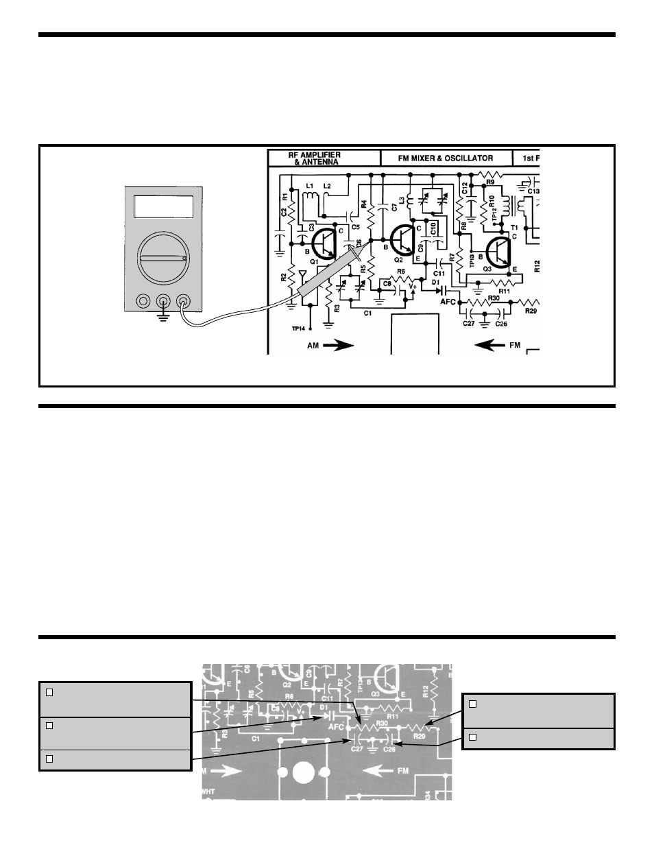
STATIC MEASUREMENTS
Figure 40
R30 - 390k
Ω
Resistor
(orange-white-yellow-gold)
D1 - Varactor Diode
(see Figure D)
C27 - .001
μ
F Discap (102)
R29 - 390k
Ω
Resistor
(orange-white-yellow-gold)
C26 - .1
μ
F Discap (104)
COM V
V
When a radio is tuned to a station, it would be
desirable for the radio to “lock” in on the station. Due
to changes in temperature, voltage and other effects,
the local oscillator may change its frequency of
oscillation. If this occurs, the center frequency of
10.7MHz will not be maintained. Automatic
Frequency Control (AFC) is used to maintain the
10.7MHz center frequency. When the local oscillator
drifts, the ratio detector will produce a DC
“correction” voltage. The audio signal rides on this
DC correction voltage. This signal is fed to a filter
network which removes the audio so that a pure DC
voltage is produced. This voltage is fed to a special
diode called a varactor. A varactor will change its
internal capacitance when a voltage is applied. The
ratio detector diodes are positioned in such a way
that when the 10.7MHz center frequency increases,
the DC correction voltage will decrease. Likewise,
when the 10.7MHz center frequency decreases, the
DC correction voltage will increase. This voltage
change causes the capacitance of the varactor to
change. The varactor is connected at the emitter of
Q2, so any capacitance change in the varactor is
seen at the emitter of the oscillator. A change in
capacitance at the emitter of Q2 will change the
frequency of oscillation of the local oscillator.
Connect your VOM to the circuit as shown in Figure 40.
Set your VOM to read 9 volts and turn the power ON.
The voltage at the base of Q2 should be about 4
volts. Turn the power OFF. If you do not get this
measurement, check R4, R5 and Q2.
AFC ASSEMBLY INSTRUCTIONS
AFC
Q2 BIAS
TP15