Assembly instructions – Elenco SEE AMFM108CK User Manual
Page 8
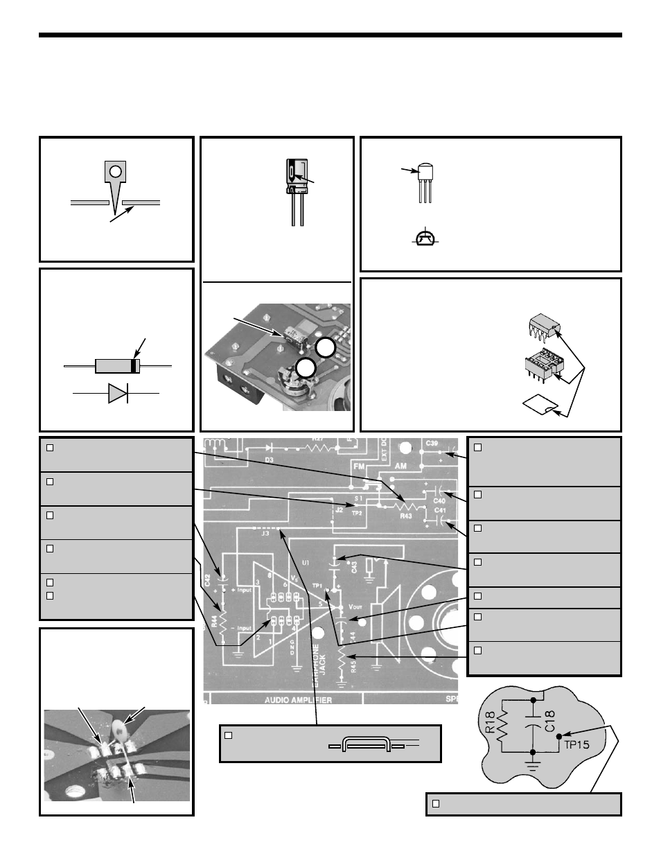
Diode
Test Point Pin
ASSEMBLY INSTRUCTIONS
We will begin by installing resistor R43. Identify the resistor by its color and install as shown on page 4. Be
careful to properly mount and solder all components. Diodes, transistors and electrolytic capacitors are
polarized, be sure to follow the instructions carefully so that they are not mounted backwards. Check the box
when you have completed each installation.
Wear safety goggles during all assembly stages in this manual.
Foil side of PC board
Figure A
NPN Transistor
Figure C
Mount so E lead is in the arrow
hole and flat side is in the same
direction as shown on the top
legend. Leave 1/4” between the
part and PC board.
Figure D
-7-
EBC
E
B
C
Flat side
Band
Cathode
Anode
Integrated Circuit
C39 - 470
μ
F Lytic
(see Figure Ba)
Mount on copper side.
C40 - 10
μ
F Lytic
(see Figure B)
C41 - 10
μ
F Lytic
(see Figure B)
C43 - 470
μ
F Lytic
(see Figure B)
C44 - .047
μ
F Discap (473)
TP1 - Test Point Pin
(see Figure A)
R45 - 10
Ω
Resistor
(brown-black-black-gold)
R43 - 100
Ω
Resistor
(brown-black-brown-gold)
TP2 - Test Point Pin
(see Figure A)
C42 - 10
μ
F Lytic
(see Figure B)
R44 - 47
Ω
Resistor
(yellow-violet-black-gold)
U1 - IC Socket 8-pin
U1 - LM386 Integrated Circuit
(see Figure E)
1/8”
Notch
J3 - Jumper Wire
(use a discarded lead)
TP-15 - Test Point Pin (see Figure A)
Lytic Capacitor
Figure B
Be sure that the
negative lead is
in the correct
hole on the PC
board.
Warning:
If the capacitor is connected with
incorrect polarity, it may heat up
and either leak, or cause the
capacitor to explode.
Figure Ba
Polarity
Mark
+
–
Be sure that the band is in
the same direction as
marked on the PC board.
Figure E
r
Insert the IC socket into the
PC board with the notch in
the direction shown on the
top legend. Solder the IC
socket into place.
r
Insert the IC into the socket
with the notch in the same
direction as the notch on the
socket.
'
Polarity
mark
(–)
(+)
0.1
μ
F Capacitor
Pin 2
r
C45 - Solder the 0.1
μ
F
capacitor across pins 2 & 6
of IC U1 as shown. The
capacitor prevents the IC
from oscillating.
Pin 6