Bandwidth test, Fm oscillator assembly instructions – Elenco SEE AMFM108CK User Manual
Page 44
-43-
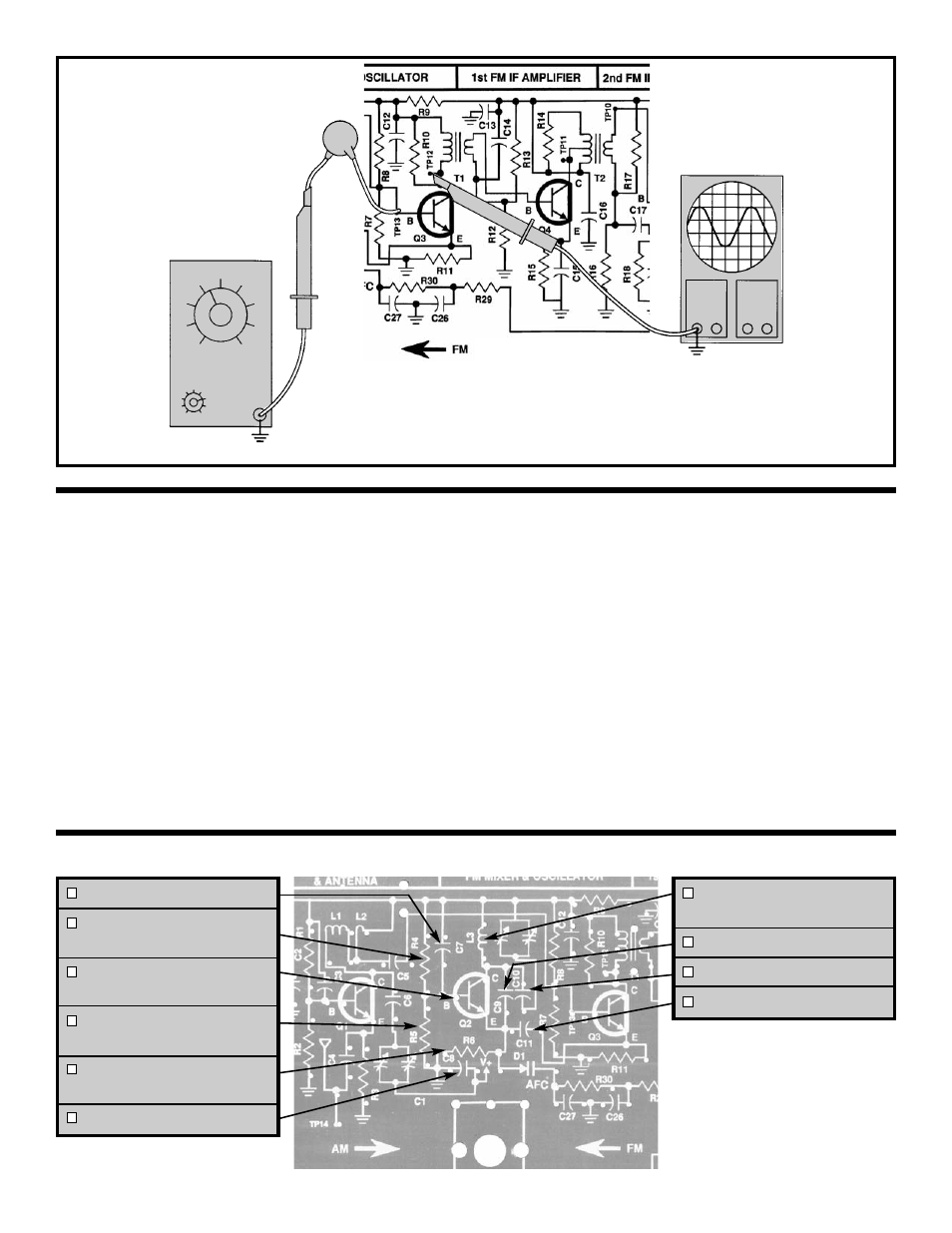
BANDWIDTH TEST
Figure 39
C7 - .001
μ
F Discap (102)
R4 - 33k
Ω
Resistor
(orange-orange-orange-gold)
Q2 - 2N3904 Transistor
(see Figure C)
R5 - 33k
Ω
Resistor
(orange-orange-orange-gold)
R6 - 2.2k
Ω
Resistor
(red-red-red-gold)
C8 - .005
μ
F Discap (502)
L3 - FM Oscillator Coil
(5 Turns)
C9 - 15pF Discap (15)
C10 - 30pF Discap (30)
C11 - 220pF Discap (221)
TP15
GENERATOR
Hz
TP15
.001
μ
F
Connect your test equipment to the circuit as
shown in Figure 39. Set your generator at 10.7MHz
no modulation and minimum voltage output. Set
the scope for 10mV per division. Turn the power
ON and slowly increase the amplitude of the
generator until 40mVpp are seen on the scope.
Increase the frequency until the voltage drops .707
of its original value, 2.8 divisions or 28mVpp.
Record the frequency of the generator until the
voltage drops .707 of its original value, 2.8 divisions
or 28mVpp. Record the frequency of the low 3dB
drop-off point here:
Fl = _________MHz.
Turn the power OFF. The bandwidth can be
calculated as follows:
Bandwidth = Fh - Fl
Your calculated answer should be between 300 -
500kHz.
Record your calculation:
Bandwidth = _________kHz.
FM OSCILLATOR ASSEMBLY INSTRUCTIONS