Elenco SEE AMFM108CK User Manual
Page 41
-40-
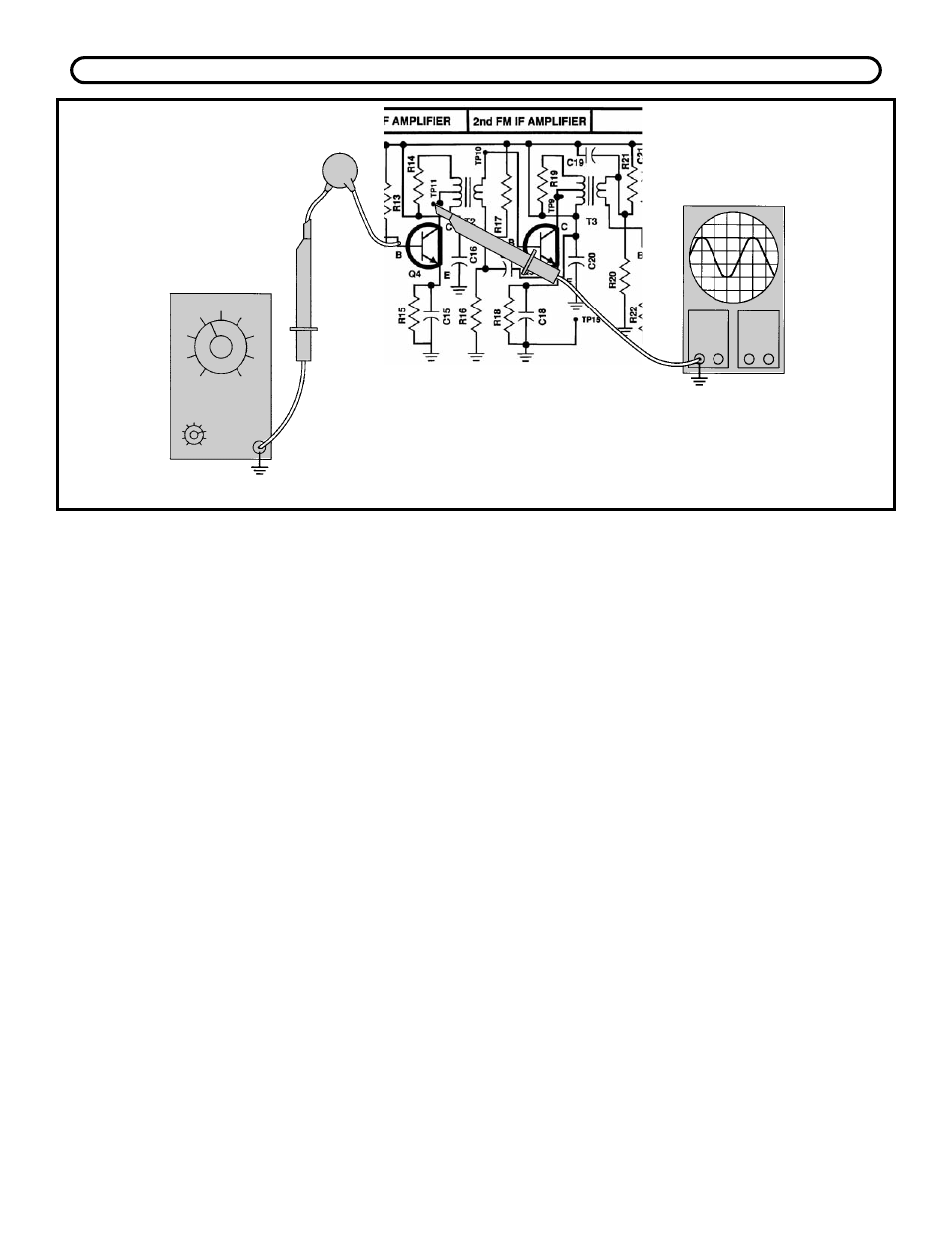
Figure 37
GENERATOR
Hz
TP15
.001
μ
F
TP15
Connect the RF generator and oscilloscope and
oscilloscope to the circuit as shown in Figure 37. The
scope probe must have an input capacitance of 12pF
or less otherwise the probe will detune T2 causing an
incorrect measurement of AC gain. Set the
generator at 10.7MHz no modulation and minimum
voltage output. Set the scope to read 20mV per
division and turn the power ON. Slowly increase the
amplitude of the generator until 3 divisions or
60mVpp are seen on the scope. With an alignment
tool or screwdriver, adjust T2 for a peak. Reduce the
generator input to maintain 3 divisions on the scope.
Move the scope probe to the base of Q4 and record
the input voltage here:
Vb = __________mVpp.
Turn the power OFF. The AC gain can be calculated
as follows:
AC Gain = 60mV / Vb
Your calculated answer should be about 10.
Record your calculation:
AC Gain = __________
BANDWIDTH
Connect your test equipment as shown in Figure 37.
Set your generator at 10.7MHz no modulation and
minimum voltage output. Set the scope to read
20mV per division. Turn the power ON and slowly
increase the amplitude of the generator until 60mVpp
is seen on the scope. Increase the frequency of the
generator until the voltage drops .707 of its original
value, 2.1 divisions or 42mVpp.
Record the frequency of the high 3dB drop-off point
here:
Fh = ___________MHz.
Decrease the frequency of the generator until the
voltage drops to .707 of its original value, 2.1
divisions or 42mVpp. Record the frequency of the
low 3dB drop-off point here:
Fl = ___________MHz.
The bandwidth of the first IF can be calculated as
follows:
Bandwidth = Fh - Fl
Your calculated answer should be between 300 -
500kHz.
Record your calculation:
Bandwidth = __________kHz.
If you don’t have an RF generator and oscilloscope, skip to Section 9.