Assembly instructions – Elenco SEE AMFM108CK User Manual
Page 34
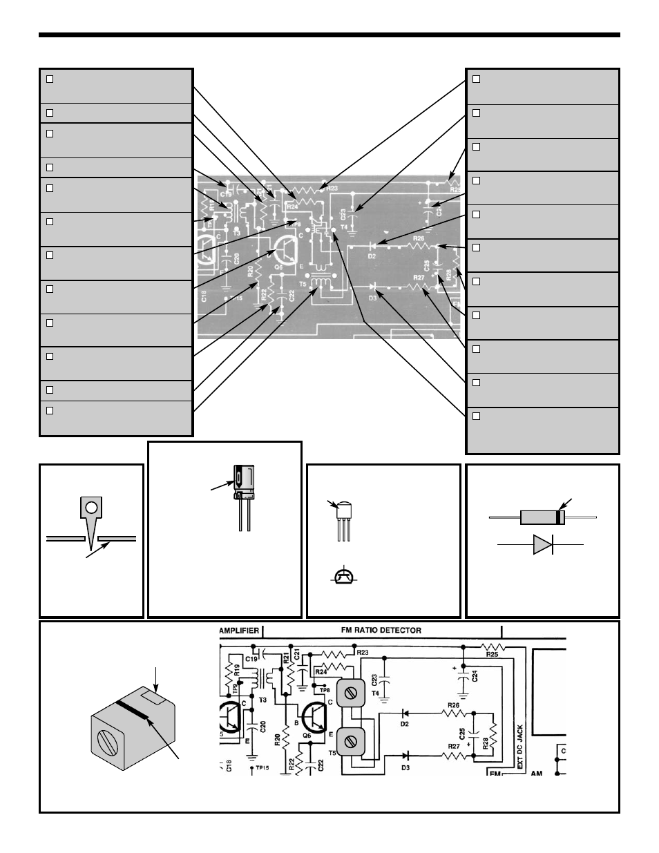
FM Detector Coil (T4)
-33-
ASSEMBLY INSTRUCTIONS
Test Point Pin
Foil side
of PC board
Figure A
Lytic Capacitor
Figure B
Be sure that the negative lead is in
the correct hole on the PC board.
NPN Transistor
Figure C
Mount so E lead is
in the arrow hole
and flat side is in
the same direction
as shown on the
top legend. Leave
1/4” between the
part and PC board.
EBC
E
B
C
Note: The line or notch must be pointing to the top of the PC board.
Some FM detector coils have a part number in place of the line/notch.
Figure 27
Flat
side
Diode
Figure D
R24 - 1k
Ω
Resistor
(brown-black-red-gold)
C21 - .01
μ
F Discap (103)
R21 - 47k
Ω
Resistor
(yellow-violet-orange-gold)
C19 - .01
μ
F Discap (103)
T3 - FM IF Coil
(Green Dot)
TP9 - Test Point Pin
(see Figure A)
TP8 - Test Point Pin
(see Figure A)
Q6 - 2N3904 Transistor
(see Figure C)
R20 - 10k
Ω
Resistor
(brown-black-orange-gold)
R22 - 1k
Ω
Resistor
(brown-black-red-gold)
C22 - .01
μ
F Discap (103)
T5 - FM Detector Coil
(Blue Dot)
R23 - 100
Ω
Resistor
(brown-black-brown-gold)
C23 - .02
μ
F Discap (203)
or .022
μ
F Discap (223)
R25 - 220
Ω
Resistor
(red-red-brown-gold)
C24 - 470
μ
F Lytic
(See Figure B)
D2 - 1N34A Diode
(see Figure D)
R26 - 1k
Ω
Resistor
(brown-black-red-gold)
R28 - 10k
Ω
Resistor
(brown-black-orange-gold)
C25 - 10
μ
F Lytic
(see Figure B)
R27 - 1k
Ω
Resistor
(brown-black-red-gold)
D3 - 1N34A Diode
(see Figure D)
T4 - FM Detector Coil
(Pink Dot)
(see Figure 27)
Polarity mark
(–)
(+)
Be sure that the band is in the same
direction as marked on the PC board.
Notch
Band
Cathode
Anode
Line
Warning:
If the capacitor is
connected with incorrect polarity,
it may heat up and either leak, or
cause the capacitor to explode.