Dynamic measurements, Ratio detector alignment – Elenco SEE AMFM108CK User Manual
Page 36
DYNAMIC MEASUREMENTS
AC GAIN
-35-
TP15
TP15
.001
μ
F
Generator
Generator
.001
μ
F
Figure 31
Hz
Hz
TP15
If you don’t have an RF generator and oscilloscope, skip to Section 7.
The AC gain of the ratio detector is set by the AC
impedance of the primary side of T4 and the current
through Q6. The current is set by R20, R21 and R22.
Capacitors C22 and C19 bypass the AC signal to
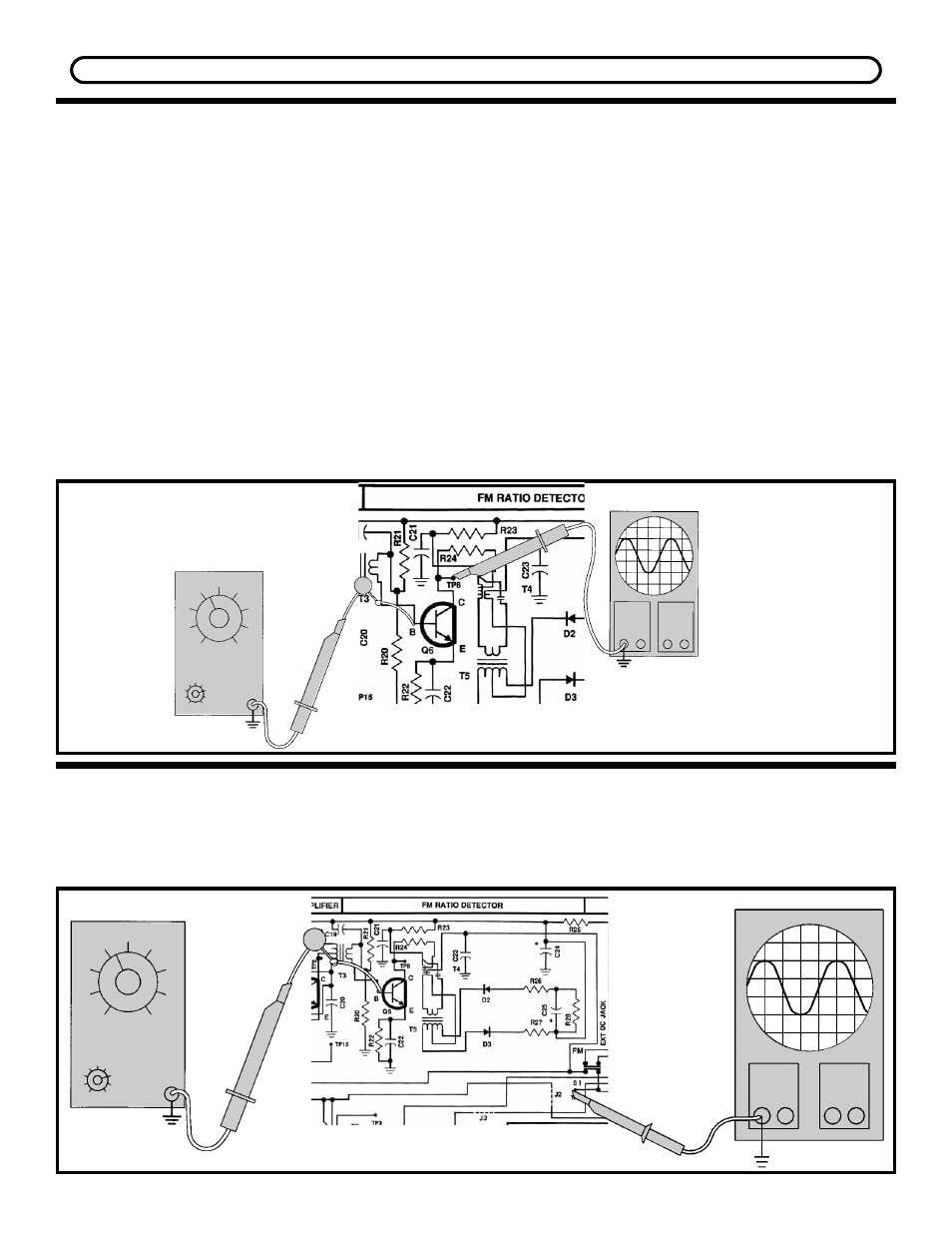
ground.Connect your RF generator and oscilloscope
to the circuit as shown in Figure 30.
Your scope probe must have an input capacitance of
12pF or less, otherwise the probe will detune T4
causing an incorrect measurement of the AC gain.
Set the generator for 10.7MHz no modulation and
minimum voltage output. Set the scope to read
50mV/division. Turn the power ON and slowly
increase the amplitude of the generator until 3
divisions or 150mVpp are seen on the scope. With
an alignment tool or screwdriver, adjust T4 for a
peak. Reduce the generator input to maintain
150mVpp on the scope. Move the scope probe to
the base of Q6 and record the voltage here:
Vb = __________ mVpp.
Turn the power OFF. The AC gain can be calculated
as follows:
AC Gain = 150mV / Vb
Your calculated answer should be approximately 20.
Record your calculation:
AC Gain = __________
With an alignment tool or a screwdriver, turn both
coils T4 and T5 fully counter-clockwise until they
stop. DO NOT FORCE THE COILS ANY FURTHER.
Now turn both coils in about 1 1/4 to 1 1/2 turns.
RATIO DETECTOR ALIGNMENT
METHOD #1
ALIGNMENT WITH NO TEST EQUIPMENT
Figure 30
TP15