Assembly instructions static tests – Elenco SEE AMFM108CK User Manual
Page 38
-37-
ASSEMBLY INSTRUCTIONS
STATIC TESTS
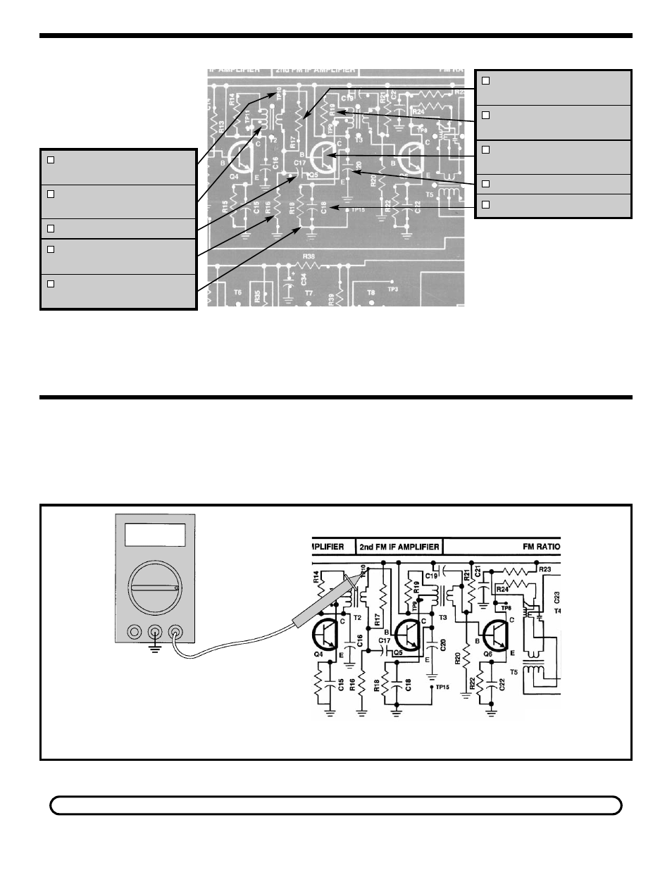
Q5 BIAS
Figure 34
TP10 - Test Point Pin
(see Figure A)
T2 - FM IF Coil
(Green Dot)
C17 - .01
μ
F Discap (103)
R16 - 10k
Ω
Resistor
(brown-black-orange-gold)
R18 - 1k
Ω
Resistor
(brown-black-red-gold)
R17 - 47k
Ω
Resistor
(yellow-violet-orange-gold)
R19 - 10k
Ω
Resistor
(brown-black-orange-gold)
Q5 - 2N3904 Transistor
(see Figure C)
C20 - .01
μ
F Discap (103)
C18 - .01
μ
F Discap (103)
TP15
COM V
V
Connect your VOM to the circuit as shown in Figure 34.
Turn the power ON. The voltage at the base of Q5
should be approximately 1.4 volts. Turn the power
OFF. If you do not get this reading, check R17, R16,
R18, Q5 and T2.
If you don’t have an RF generator and oscilloscope, skip to Section 8.
See also other documents in the category Elenco Measuring instruments:
- Computer Inteface for Snap Circuits® (60 pages)
- Capacitor Substitution Box (8 pages)
- Diode/Transistor Tester Kit (12 pages)
- Diode/Transistor Tester (8 pages)
- Electronic Component Kit (28 pages)
- 100kHz Function Generator in Kit Form (16 pages)
- 100kHz Function Generator (8 pages)
- Surface Mount Generator Kit (16 pages)
- 5MHz Function Generator (12 pages)
- 015V Power Supply Kit (8 pages)
- Resistor Substitution Box (8 pages)
- 3 3/4 Digit Cap./Ind./Logic (2 pages)
- Logic Probe Kit (12 pages)
- Logic Pulser Kit (12 pages)
- Compact Digital Multimeter (20 pages)
- Digital Multimeter (18 pages)
- 3 1/2 Digit Cap. / Trans. Kit (36 pages)
- Compact Multimeter (8 pages)
- Digital Mulitmeter Kit (20 pages)
- 23 Range 20k/V VOM in Kit Form (20 pages)
- 3 1/2 Digit Cap./ Freq./ Trans. w/ Grey Boot (8 pages)
- 3 1/2 Digit with Temperature (36 pages)
- 3 1/2 Digit Cap./ Trans./ Freq (4 pages)
- Digital Bench Multimeter (26 pages)
- MicroMaster ® Computer Training Kit (116 pages)
- 100MHz Scope (68 pages)
- Wide Band RF Generator (7 pages)
- Deluxe Solar Educational Kit (15 pages)
- Soldering Station (6 pages)
- Soldering Station (20 pages)
- Soldering Station (4 pages)
- Surface Mount Technology Kit (12 pages)
- Practical Soldering Project Kit (16 pages)
- DataCom Tester Kit (28 pages)
- MultiModular Cable Tester (4 pages)
- Tone Generator (4 pages)
- Telephone Line Analyzer Kit (16 pages)
- Digital / Analog Trainer Kit Version (52 pages)
- Digital / Analog Trainer in Case (16 pages)
- Deluxe Digital / Analog Trainer with Tools Kit Version (52 pages)
- Digital / Analog Trainer (12 pages)
- Deluxe Digital / Analog Trainer (16 pages)
- Variable Voltage Power Supply Kit (12 pages)
- Variable Voltage Power Supply (8 pages)