X2 x3, Receiver alignment (highly recommended) – Elenco Radio Controlled Car Soldering User Manual
Page 27
-26-
21
Screws Used
(shown actual size)
0.3” x 0.1”,
0.2” head
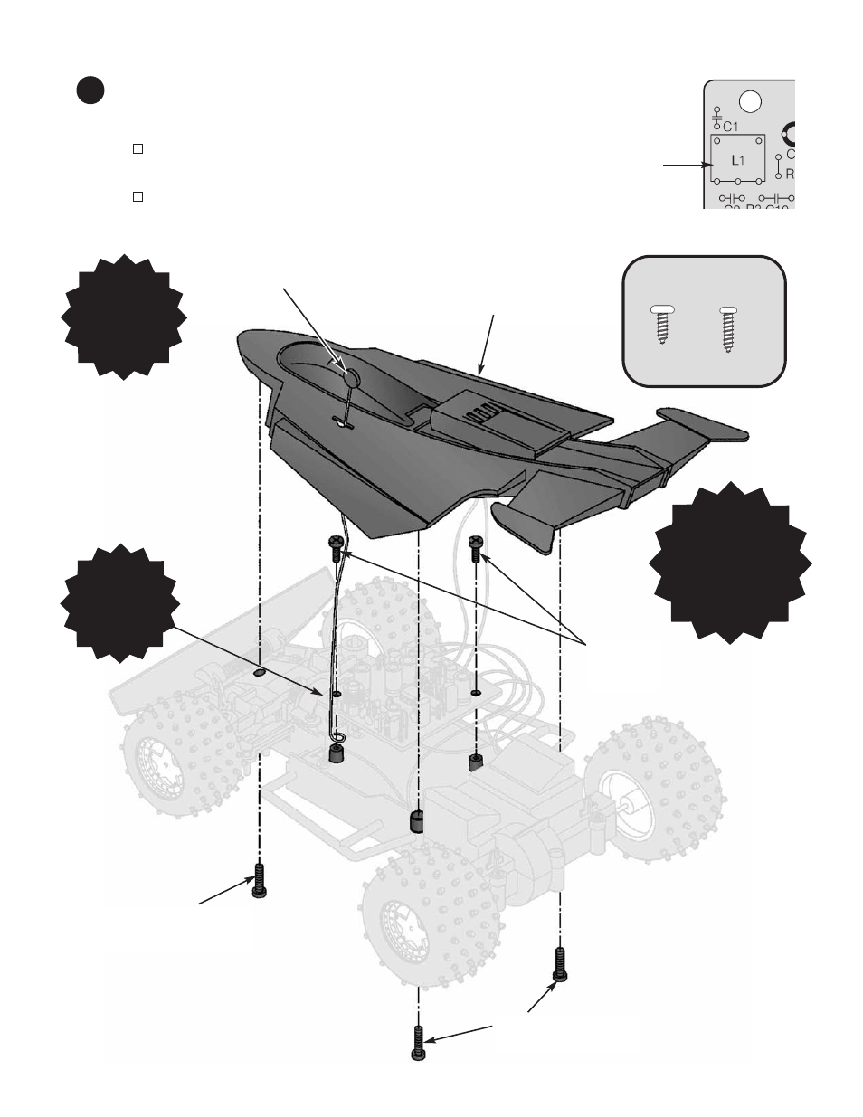
Top Frame
Car Antenna
X2
X3
0.4” x 0.1”,
0.15” head
0.4” x 0.1”, 0.15” head
Screw
0.4” x 0.1”, 0.15” head
Screws
0.3” x 0.1”,
0.2” head
Screws
NOTE: Be careful
not to stress or break
any of the wires and
connections. You may
also want to tape the
wires down to keep
them inside the car.
NOTE: Insert
the antenna
through the top
cover before
screwing it down.
Receiver Alignment (highly recommended)
Although tunable inductor L1 has been pre-aligned, you may adjust it for optimum performance. You need
a very small screwdriver for this.
The Car Antenna must be screwed together with the PCB and bottom frame as shown below, to make
a good connection. Flip the ON/OFF switches to on. Activate the transmitter and move it away from the
car. (This is difficult to do by yourself unless you use a rubber band to keep the transmitter activated.)
Adjust tunable inductor L1 for best range. Be VERY GENTLE, since L1 is FRAGILE. It should turn
easily. If you apply too much force you may break it.
Turn the ON/OFF switches to off.
NOTE: Orient
the PC board so
that L1 is on the
left side of the
car.