Resistance tests, Interconnections & testing, Ground wire – Elenco Radio Controlled Car Soldering User Manual
Page 22: Wire
Resistance Tests
Remove one or all of the “AA” batteries from the car
for these tests.
Switch connections: Using a multimeter set to
ohms, measure from the front-left battery contact
(which has a wire to the ON/OFF switch) to
where you soldered the red wire (also from the
ON/OFF switch) to the printed circuit board
(PCB).
This should be 0
Ω
when the ON/OFF
switch is ON and infinite when the switch is OFF.
Vcc to ground: Set the ON/OFF switch to ON.
Measure from the front-left battery contact to the
front-right battery contact (which has the black
wire soldered to it). The resistance will initially be
<10k
Ω
but will slowly rise to around 45k
Ω
as the
capacitors in the circuit charge up.
If you don’t get these results then re-check your
work.
-21-
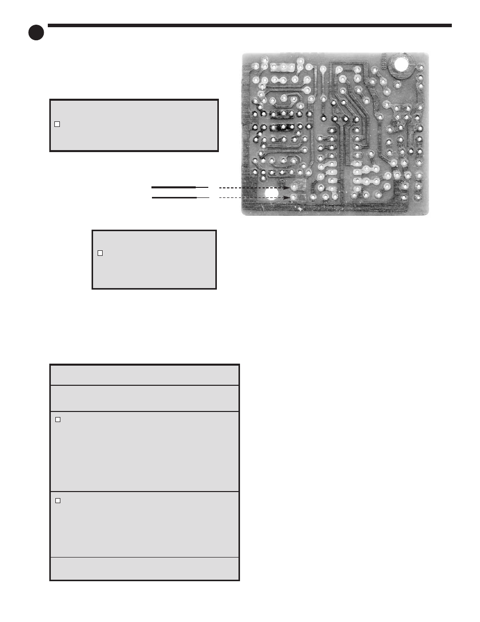
INTERCONNECTIONS & TESTING
Black wire from
battery contact
Red wire
from switch
Ground Wire
Solder the black wire from the
battery contact to this solder
pad. BE CAREFUL TO AVOID
TOUCHING NEARBY PADS!
V
cc
Wire
Solder the red wire from the ON/OFF switch
to this solder pad. BE CAREFUL TO AVOID
TOUCHING NEARBY PADS!
16