Battery tests, Driving voltage tests – Elenco Radio Controlled Car Soldering User Manual
Page 23
-22-
Battery Tests
Install 4 fresh AA alkaline (or rechargeable nickel-
cadmium) batteries in the battery cage, observing their
polarity while doing so. Caution: Do not mix alkaline,
standard (carbon-zinc), or rechargeable (nickel-
cadmium) batteries.
Snap in the battery cover to close it.
Battery Voltage: Using a multimeter set to DC volts,
measure between the front-left and front-right battery
contacts. You should measure about 6V.
Idle Current: Set the ON/OFF switch to OFF. Set your
multimeter to DC amps. Connect your probes between
the left-front battery tab and the red wire from
connection point 3 on the PCB. You should measure a
current of 18mA ± 8mA. Check your work if you don’t.
Driving Voltage Tests
Set the switch to ON and your multimeter to DC volts.
Connect (–) probe to the front-right battery contact (DC
ground) for all these tests. Activate the transmitter for
forwards/backwards while measuring the voltage at pins
10 & 11 on the SCRX2BC IC.
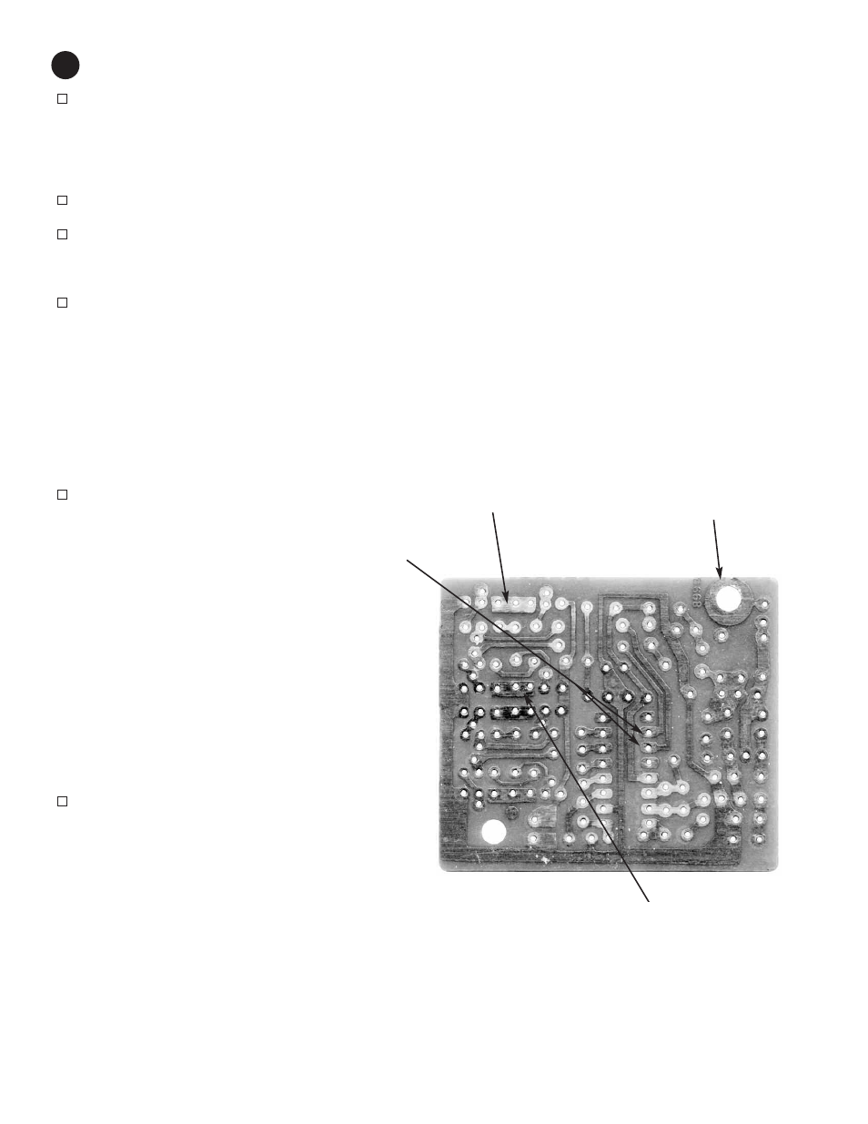
Note: You may need to clip a wire from the antenna on the
remote control unit to the antenna solder pad (next to C1),
since the car’s antenna is not attached yet.
Pin 10 Pin 11
TX: forward 0 V 3.0 ± 0.5 V
TX: backward 3.0 ± 0.5 V 0 V
If you don’t get these voltages check your receiver and
SCRX2BC support circuitry. Refer to Theory of Operation
as needed.
Similarly, measure the voltages at the Q6-Q8 and Q5-
Q7 junctions while transmitting commands:
Q6-Q8 junction Q5-Q7 junction
TX: forward 0 V 6 ± 1 V
TX: backward 6 ± 1 V 0 V
If you don’t get these voltages, check your driving circuit.
17
Q6-Q8 junction
Q5-Q7 junction
Antenna solder pad