Steering voltage tests – Elenco Radio Controlled Car Soldering User Manual
Page 24
-23-
Steering Voltage Tests
Activate the transmitter for left/right while measuring
the voltage at pins 6 & 7 on the SCRX2BC IC. (Note:
on some models the steering lever only works if you
are also pressing the forwards/backwards lever).
Notes:
You may need to touch the antenna on the remote
control unit to the antenna solder pad (next to C1), since
the car’s antenna is not attached yet.
The (–) voltage probe should be connected to DC ground
(the front-right battery contact) for all of these tests.
pin 6
pin 7
TX: left
3.0 ± 0.5 V
0 V
TX: right
0 V
3.0 ± 0.5 V
If you don’t get these voltages check your receiver and
SCRX2BC support circuitry.
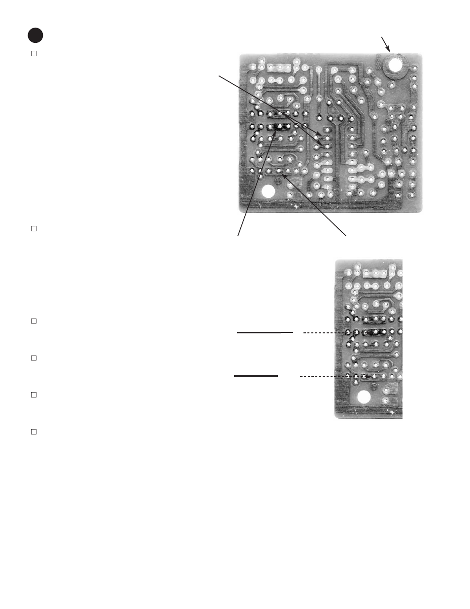
Similarly, measure the voltages at the Q12-Q14 and
Q11-Q13 junctions while transmitting commands:
Q12-Q14 junction
Q11-Q13 junction
TX: left
6 ± 1 V
0 V
TX: right
0 V
6 ± 1 V
If you don’t get these voltages check your steering
circuit.
Solder the blue wire from the steering motor to the
Q12-Q14 junction on the PCB.
BE CAREFUL TO
AVOID ALSO TOUCHING NEARBY PADS.
Solder the orange wire from the steering motor to the
Q11-Q13 junction on the PCB.
BE CAREFUL TO
AVOID ALSO TOUCHING NEARBY PADS.
Elevate the front of the car so that the front wheels
may turn freely. Activate the transmitter for left/right
and make sure the wheels turn properly.
Re-measure the voltages at PCB junctions Q12-Q14
and Q11-Q13 now that they are loaded by the
steering motor:
Q12-Q14 (loaded)
Q11-Q13 (loaded)
TX: left
5 ± 1.5 V
0.3 ± 0.3 V
TX: right
0.3 ± 0.3 V
5 ± 1.5 V
If you don’t get these voltages or the front wheels don’t
turn then check your steering circuit. You should also re-
do the motor quick test in assembly step 10.
Blue wire from
steering motor
18
Q12-Q14 junction
Q11-Q13 junction
Orange wire from
steering motor
Antenna solder pad