Final alignments – Elenco AM Radio Kit User Manual
Page 27
-26-
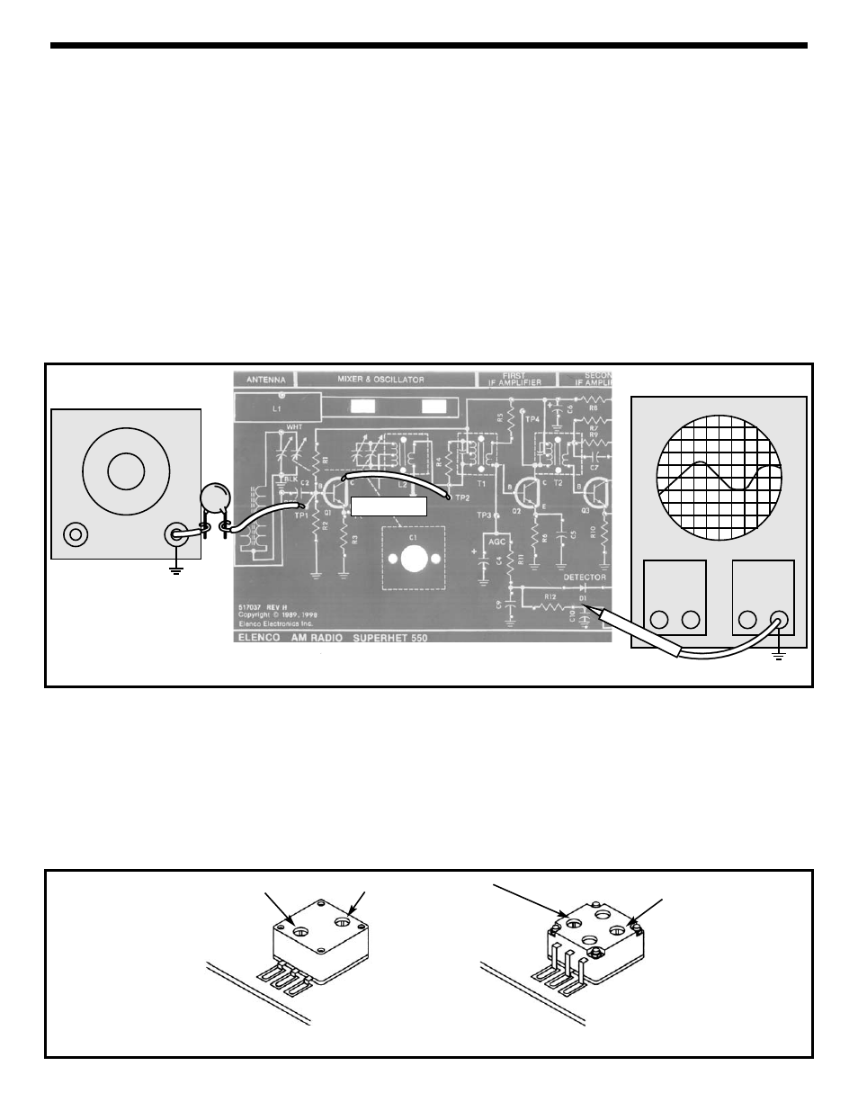
Figure 24
Antenna Trimmer
Oscillator Trimmer
Antenna Trimmer
3 Leads
4 Leads
Figure 25
FINAL ALIGNMENTS
With the power turned OFF, connect the RF generator
and the oscilloscope to your circuit as shown in Figure 24.
Short TP2 to the collector of Q1 with a clip lead to “kill”
the local oscillator. Set the RF generator at a
frequency of 455kHz, modulation of 400Hz 80%,
minimum amplitude output. Set the oscilloscope to
read 0.1Vpp and turn the power ON. Increase the
amplitude of the RF signal until the oscilloscope
registers 0.5Vpp. Align transformers T3, T2 and T1 for
the maximum AC reading on the oscilloscope.
Decrease the amplitude of the signal from the RF
generator to restore 0.5Vpp on the oscilloscope.
Repeat the last two steps until no change in the peak
at the oscilloscope is noticed.
After IF alignment, lower the frequency from the RF
generator until the reading on the VOM drops to 0.707
of its peaked value. Record the frequency of this
lower 3dB corner here:
Fl=____________kHz.
Increase the RF generator frequency past the peak to
the upper 3dB corner and record that frequency here:
Fh=____________kHz.
The bandwidth of the IF amplifiers is BW=Fh - Fl. IF
bandwidth should be between 1 to 2kHz. This
bandwidth will widen as the AGC is approached.
IF BANDWIDTH
With the power turned OFF, connect the equipment to
the circuit as shown in Figure 24. DO NOT connect
the clip lead from TP2 to Q1. Set the RF generator at
540kHz, 400Hz 80% modulation, and a low level of
output. Turn the tuning capacitor fully counter-
clockwise. Turn the power ON and a 400Hz tone
should be heard coming from the speaker. Tune the
oscillator coil (L2) for a peak on the oscilloscope.
Adjust the RF generator output during this process to
maintain a peak at 0.5Vpp or less. After peaking L2,
set the RF generator frequency to 1600kHz and turn
the tuning capacitor (C1) fully clockwise. A 400Hz
tone should be heard coming from the speaker. Tune
the oscillator trimmer capacitor on the back of C1 for
a peak on the oscilloscope (see Figure 25).
SETTING OSCILLATOR RANGE
.02
μF
Output
Adjust
Oscilloscope
Generator
TP8
TP8
Clip Lead
Probe