Second if amplifier, Assembly instructions - second if amplifier – Elenco AM Radio Kit User Manual
Page 19
-18-
TP4 - Test Point Pin
(see Figure E)
T2 - IF Coil
(White Dot)
Q3 - 2N3904 Transistor NPN
(see Figure G)
R10 - 470
Ω Resistor
(yellow-violet-brown-gold)
R7 - 39k
Ω Resistor
(orange-white-orange-gold)
R9 - 10k
Ω Resistor
(brown-black-orange-gold)
C7 - .02
μF Discap (203)
or .022
μF Discap (223)
C8 - .02
μF Discap (203)
or .022
μF Discap (223)
SECTION 3
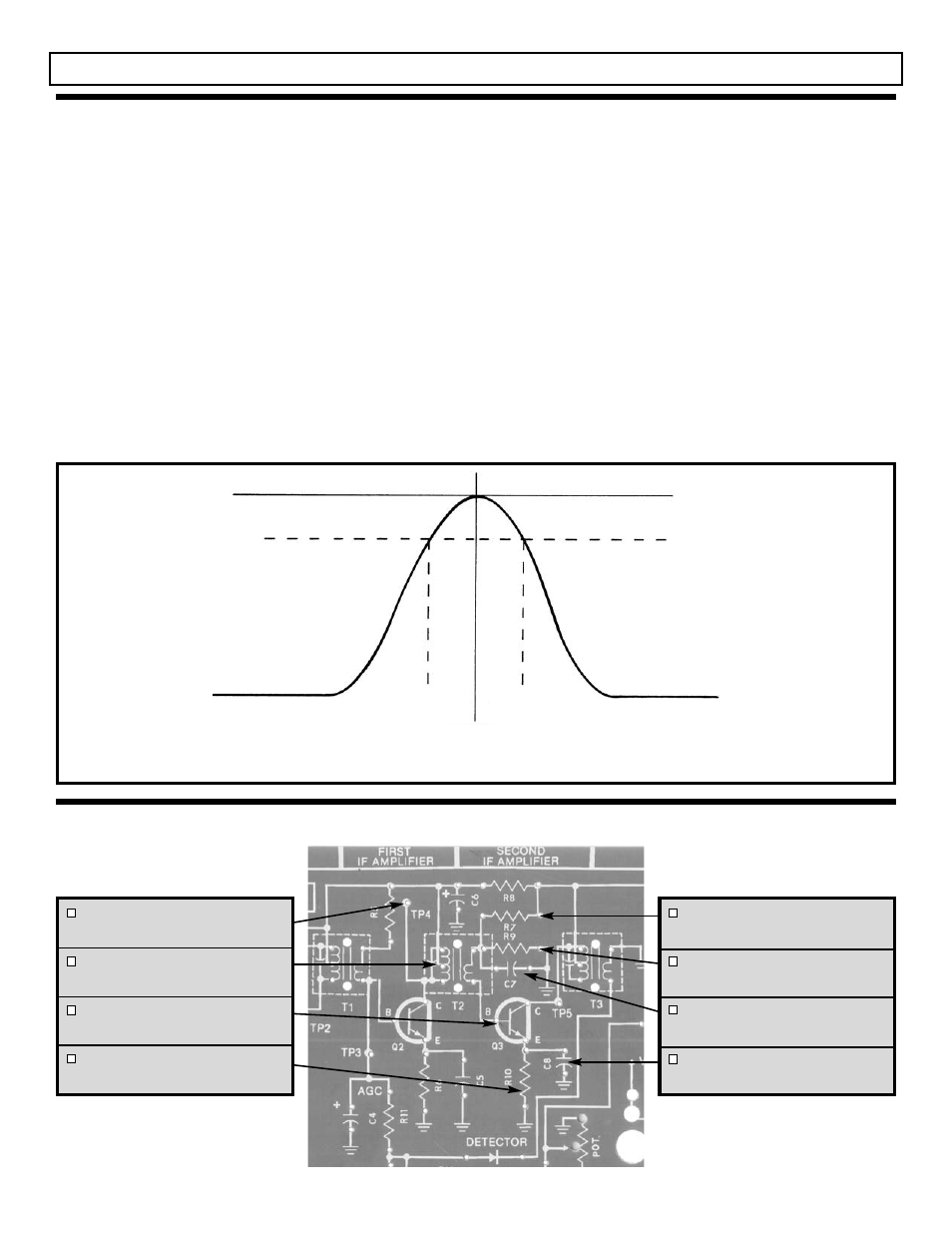
Figure 17
.707
452kHz
458kHz
455kHz
The purpose of the SECOND IF AMPLIFIER is to
increase the amplitude of the intermediate frequency
(IF) and at the same time provide SELECTIVITY.
Selectivity is the ability to “pick out” one radio station
while rejecting all others. The second IF transformer
(T3) acts as a bandpass filter with a 3dB bandwidth
of approximately 6kHz. The amplitude versus
frequency response of the second IF amplifier is
shown in Figure 17.
Both IF amplifiers are tuned to a frequency of
455kHz and only need to be aligned once when the
radio is assembled. These amplifiers provide the
majority of the gain and selectivity needed to
separate the radio stations.
The gain at 455kHz in the second IF amplifier is fixed
by the AC impedance of the primary side of
transformer T3, and the DC current in Q3. The
current in Q3 is set by resistors R7, R9 and R10.
Both C7 and C8 bypass the 455kHz signal to ground,
making Q3 a common emitter amplifier. The signal is
coupled from the first IF amplifier to the second IF
amplifier through transformer T2. The IF
transformers not only supply coupling and selectivity,
they also provide an impedance match between the
collector of one stage and the base of the next stage.
This match allows maximum power to transfer from
one stage to the next.
SECOND IF AMPLIFIER
THEORY OF OPERATION
ASSEMBLY INSTRUCTIONS - SECOND IF AMPLIFIER