Assembly instructions – Elenco AM Radio Kit User Manual
Page 11
-10-
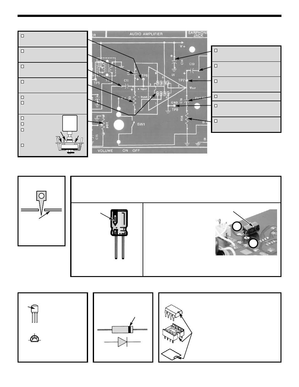
ASSEMBLY INSTRUCTIONS
Diode
Be sure that the band is in
the correct direction.
NPN Transistor
Figure G
Mount so E lead is
in the arrow hole
and flat side is in
the same direction
as shown on the
top legend. Leave
1/4” between the
part and PC board.
Figure H
EBC
E
B
C
Flat
Side
Band
Cathode
Anode
Integrated Circuit
Insert the IC socket into the
PC board with the notch in
the direction shown on the
top legend. Solder the IC
socket into place. Insert the
IC into the socket with the
notch in the same direction
as the notch on the socket.
C14 - 470
μF Lytic Capacitor
(see Figure Fa
C13 - 470
μF Lytic Capacitor
(see Figure F)
TP7 - Test Point Pin
(see Figure E)
C16 - .047
μF (473) Discap
TP8 - Test Point Pin
(see Figure E)
R14 - 10
Ω 5% 1/4W Resistor
(brown-black-black-gold)
Figure I
Notch
TP6 - Test Point Pin
(see Figure E)
C12 - 10
μF Lytic Capacitor
(see Figure F)
C11 - 10
μF Lytic Capacitor
(see Figure F)
R13 - 47
Ω 5% 1/4W Resistor
(yellow-violet-black-gold)
U1 - IC Socket 8-Pin
U1 - Integrated Circuit LM-386
(see Figure I)
Pot with Switch
Nut & Washer
Knob
Solder 5 lugs
to PC board.
Top Side
Test Point Pin
Foil Side
of PC Board
Figure E
Nut
Washer
Electrolytics have a polarity marking indicating the
(–) lead. The PC board is marked to show the lead
position.
Warning: If the capacitor is connected with
incorrect polarity, or if it is subjected to voltage
exceeding its working voltage, it may heat up and
either leak or cause the capacitor to explode.
Polarity Mark
Polarity Mark
Capacitor C14
For safety, solder capacitor C14
on the copper side as shown.
Bend the leads 90
O
and insert
into holes. Check that the
polarity is correct, then solder in
place. Trim the excess leads on
legend side.
Figure F
Figure Fa
(–)
(+)
+
–