Static measurements, Dynamic measurements – Elenco AM Radio Kit User Manual
Page 26
-25-
Figure 23
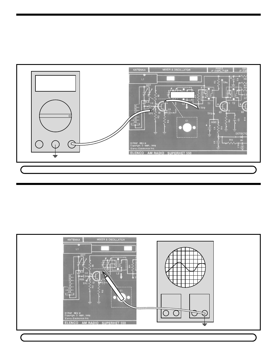
Figure 22
STATIC MEASUREMENTS
With the power turned OFF, connect the VOM to your
circuit as shown in Figure 22. Connect a clip lead from
test point two (TP2) to the collector of Q1. This short
prevents Q1 from oscillating. Set the VOM to read 2
volts DC accurately and turn the power ON. The DC
voltage at TP1 should be 1.6 volts. If the voltage in
your circuit differs by more than 0.5 volts, leave the
power ON and check the battery voltage. If the battery
voltage is greater than 8.5 volts, turn the power OFF
and check components R1, R2, R3 and Q1.
Q1 BIAS
If you do not have an oscilloscope, go to the Final Alignments With No Test Equipment Section.
DYNAMIC MEASUREMENTS
With the power turned OFF, connect the oscilloscope
to the circuit as shown in Figure 23.
Set the oscilloscope for a vertical sensitivity of 1
volt/division and turn the power ON. The oscilloscope
should display a low voltage sine wave. The
frequency of the sine wave should change when
capacitor C1 is turned. If your circuit fails this test,
turn the power OFF and check components Q1, C1,
C2, C3, L1 and L2.
OSCILLATOR CIRCUIT
If you do not have an RF generator, go to the Final Alignments with No Test Equipment Section.
V
Ohms
COM
V
Oscilloscope
TP8
TP8
Clip Lead