First if amplifier, Assembly instructions - first if amplifier – Elenco AM Radio Kit User Manual
Page 21
-20-
R4 - 1M
Ω Resistor
(brown-black-green-gold)
TP2 - Test Point Pin
(see Figure E)
Q2 - 2N3904 Transistor NPN
(see Figure G)
R6 - 1k
Ω Resistor
(brown-black-red-gold)
C5 - .02
μF Discap (203)
or .022
μF Discap (223)
SECTION 4
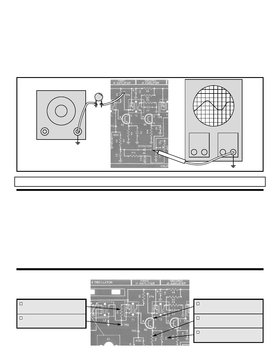
Figure 20
With the power OFF, connect your equipment as shown in
Figure 20. Turn the power ON and adjust the RF
generator for .4Vpp at the cathode of D1. If necessary,
realign transformer T3 for maximum output while adjusting
the output of the RF generator to maintain .4Vpp. Slowly
decrease the frequency of the RF generator until the
signal drops to .707 of its peaked value or .28Vpp. Record
the frequency of the RF generator here:
FL=___________kHz.
Now increase the frequency of the RF generator past the
peak to a point where the signal drops to .707 of its peak
value. Record that frequency point here:
FH=___________kHz. By subtracting the frequency of
the lower 3dB corner from the frequency of the higher 3dB
corner you get the BANDWIDTH of the second IF
amplifier. Your results should be similar to the values
shown in Figure 17.
BANDWIDTH TEST
FIRST IF AMPLIFIER
The operation of the first IF amplifier is the same as for the
second IF amplifier with one important difference. The
gain of the first IF amplifier decreases after the AGC
threshold is passed to keep the audio output constant at
the detector and prevent overload of the second IF
amplifier. This is accomplished by making the voltage on
the base of transistor Q2, lower as the signal strength
increases. Since the voltage from base to emitter is fairly
constant, the drop in voltage at the base produces a
similar drop in voltage at the emitter of Q2. This drop
lowers the voltage across R6 and thus reduces the DC
current through R6. Since all of the DC current from the
emitter of Q2 must go through R6, the DC current in Q2 is
therefore lowered. When the DC current in a transistor is
lowered, its effective emitter resistance increases. The AC
gain of transistor Q2 is equal to the AC collector load of Q2
divided by its effective emitter resistance. Raising the
value of the effective emitter resistance thus lowers the AC
gain of Q2.
THEORY OF OPERATION
Oscilloscope
Generator
.02
μF
Output
Adjust
TP8
TP8
Probe
ASSEMBLY INSTRUCTIONS - FIRST IF AMPLIFIER