Dynamic measurements – Elenco AM Radio Kit User Manual
Page 18
-17-
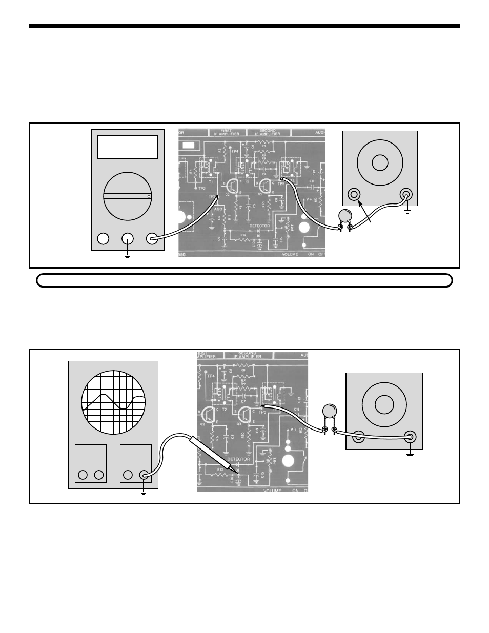
Figure 15
DYNAMIC MEASUREMENTS
Turn the power OFF and connect the VOM and RF
generator as shown in Figure 15.
Set the VOM to accurately read 2 volts DC and set
the output of the RF generator for 455kHz, no
modulation, and minimum amplitude. Turn the power
ON and slowly increase the amplitude of the 455kHz
signal from the RF generator until the voltage at TP3
just starts to drop. This point is called the AGC
threshold with no IF gain. Make a note of the
amplitude setting on the RF generator here:
____________. Turn the power OFF.
DETECTOR AND ACG TEST
If your RF generator does not have amplitude modulation or you do not have an oscilloscope, go to Section 3.
Connect equipment as shown in Figure 16.
Set the RF generator at 455kHz, 1kHz at 80%
modulation and minimum output. Turn the power ON
and put the volume control at full clockwise position.
Slowly adjust the amplitude of the RF generator
output until you hear the 1kHz on the speaker. If this
test fails, turn the power OFF and check C11, R12,
volume control, D1 and TP3.
SYSTEM CHECK
Figure 16
Connect equipment as shown in Figure 16. Set the
RF generator at 455kHz with 80% modulation at a
modulation frequency of 1kHz. Set the oscilloscope
to read .1 volts per division. Turn the power ON and
put the volume control at minimum. Increase the
amplitude of the RF generator until the signal on the
oscilloscope is 4 divisions peak to peak. Check the
signal to make sure it is free of all distortion. Leave
the frequency of the RF output at 455kHz, but
increase the modulation frequency until the output
drops to 0.28 Vpp. Record the modulation frequency
on the RF generator here:
____________
This frequency should be greater than 5kHz. Turn
the power OFF.
DETECTOR BANDWIDTH TEST
V
Amps
COM
V
TP8
Generator
TP8
Output
Adjust
.02
μF
Oscilloscope
Generator
Probe
.02
μF
TP8
TP8
Output
Adjust