Elenco AM Radio Kit User Manual
Page 16
-15-
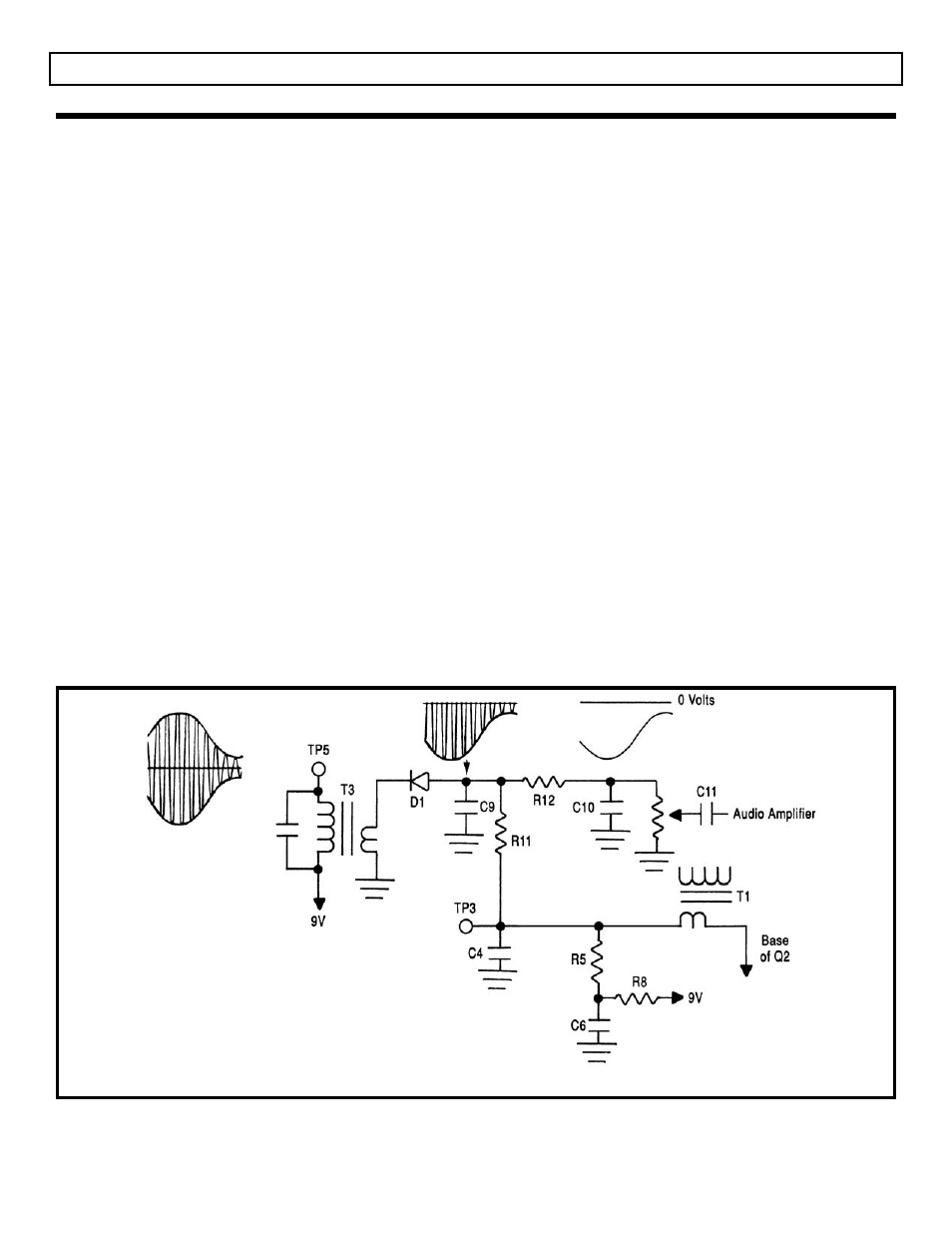
The purpose of the detector is to change the
amplitude modulated IF signal back to an audio
signal. This is accomplished by a process called
detection or demodulation. First, the amplitude
modulated IF signal is applied to a diode in such a
way as to leave only the negative portion of that
signal (see Figure 13). The diode acts like an
electronic check valve that only lets current pass in
the same direction as the arrow (in the diode symbol)
points. When the diode is in conduction (On
Condition), it will force capacitors C9 and C10 to
charge to approximately the same voltage as the
negative peak of the IF signal. After conduction
stops in the diode (Off Condition), the capacitors will
discharge through resistors R11, R12 and the
volume control. The discharge time constant for this
circuit must be small enough to follow the audio
signal or high frequency audio distortion will occur.
The discharge time constant must be large enough,
however, to remove the intermediate frequency
(455kHz) and leave only the audio at the volume
control as shown in Figure 13.
The purpose of the automatic gain control (AGC)
circuit is to maintain a constant audio level at the
detector, regardless of the strength of the incoming
signal. Without AGC, the volume control would have
to be adjusted for each station and even moderately
strong stations would clip in the final IF amplifier
causing audio distortion. AGC is accomplished by
adjusting the DC bias of the first IF amplifier to lower
its gain as the signal strength increases. Figure 13
shows that the audio at the top of the volume control
is actually “riding” on a negative DC voltage when
strong signals are encountered. This negative DC
component corresponds to the strength of the
incoming signal. The larger the signal, the more
negative the component. At test point three (TP3),
the audio is removed by a low pass filter, R11 and
C4, leaving only the DC component. Resistor R5 is
used to shift the voltage at TP3 high enough to bias
the base of transistor Q2 to the full gain position
when no signal is present. Resistors R5 and R11
also forward bias diode D1 just enough to minimize
“On Condition” threshold voltage.
SECTION 2
Figure 13
AM DETECTOR AND AGC STAGES
THEORY OF OPERATION