Project #303, Mirror circuit project #301, Alarm motor project #302 alarm light – Elenco Electronics 202 User Manual
Page 127
-126-
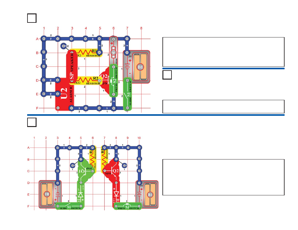
Project #303
OBJECTIVE: To build a mirror view of a circuit.
Using PNP (Q1) and NPN (Q2) transistors, you can make two circuits
that look the same, but are electrically opposite. When you turn on the
slide switch (S1), the base of Q1 connects to the negative (–) side of
the battery (B1), turning on Q1 and the green LED (D2) lights. When
you press the press switch (S2), the base of Q2 connects to the
positive (+) side of the battery, turning on Q2 and the red LED (D1)
lights.
Mirror Circuit
Project #301
OBJECTIVE: To build a circuit where the alarm IC controls the
fan speed.
Place the fan on the motor and turn on the slide switch (S1). A
machine gun sound is heard and the fan spins unevenly. The fan
speed is being controlled by the alarm IC (U2).
Now, press the press switch (S2) to control the motor directly, and the
motor spins much faster.
Alarm Motor
Project #302
Alarm Light
OBJECTIVE: To modify project #301.
Replace the motor (M1) with the 6V lamp (L2). Now the alarm IC (U2)
and press switch (S2) control the lamp brightness.