Status led 8, Status led – Eagle Tree Guardian 2D/3D Stabilizer User Manual
Page 8
Copyright 2013-2014 Eagle Tree Systems, LLC Page 8
Figure 8: LED Indication during Steady State
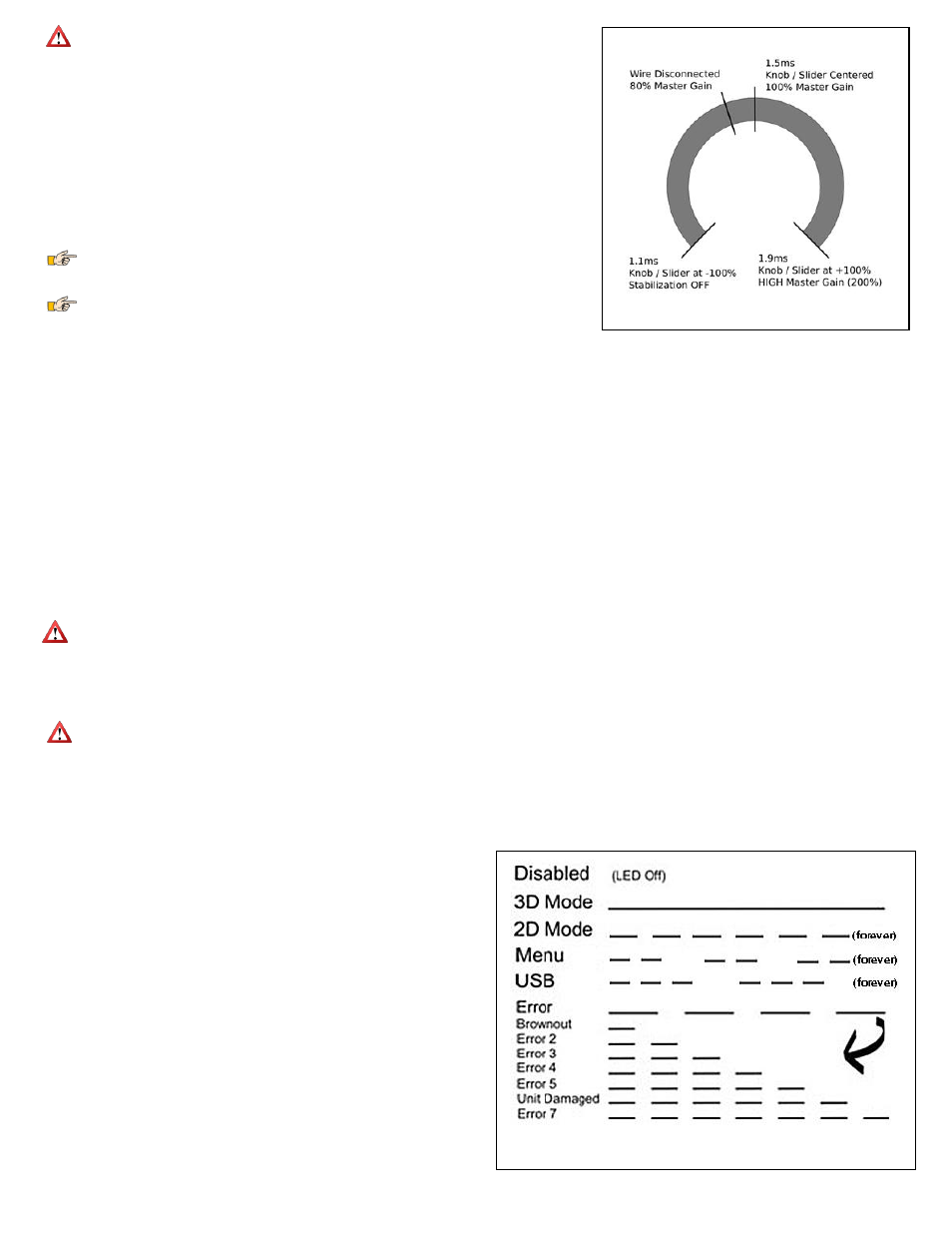
Figure 7A - Guardian Master Gain Control
Too high of a gain setting can result in oscillation: see the Oscillations section for more
information on this. Setting Master Gain control to the minimum will lower the overall gain to
zero, while positions in between will yield proportional gain. Lowering the individual gain dials on the
Guardian will lower the gain for that axis only and allow fine tuning. This might be desirable if, for instance,
oscillation is encountered on one axis but not the others.
One possible strategy for setting gains would be to set all three of the individual gain control dials to
maximum and the master to zero. While flying the plane with the Guardian engaged, slowly turn up the
Master Gain and watch for signs of oscillation. If oscillation is encountered, back down the Master Gain
until it ceases. With the plane on the ground, reduce the setting on the potentiometer for the axis for which
oscillation was observed. Repeat until the plane can be flown with the Master Gain in its middle
position without oscillation. If you have a plane with a wide speed range, such as a hovering 3D aircraft,
using this procedure using only the mid range on the Master Gain will allow you later to turn it even higher
when hovering or performing other slow speed aerobatic maneuvers as oscillation is seldom a problem
under these conditions.
If continuous oscillations are experienced with the Master Gain wire disconnected, switch the
Guardian off immediately with the Mode switch if necessary, and land. On the ground, reduce the gain dial
for the oscillating axis as described above.
If connecting the Gain channel on a model where the Guardian had been previously tuned without
it, ensure that the position of the Master Gain knob, slider or switch is set at slightly less than the centered
position (see figure 7A) to prevent the possibility of strong oscillations on takeoff.
Oscillations
Sometimes, when the controller gains are set very high or if your model flies at a very high airspeed, oscillations can develop. If oscillations occur, turn down the Master
Gain control or the gain dial for the axis that is oscillating (i.e., the Pitch axis), until the oscillations stop. Other causes of oscillations include mechanical slop in control
surfaces and slow servos. If your model has digital servos, higher gain values may be made possible by increasing the Output Servo Pulse Frequency. See: List of Menu
Features and Options: Output Servo Pulse Frequency.
Oscillation Suppression
To help reduce pilot workload, the Guardian will automatically scale down the Overall Gain when it detects oscillations. To do this, it incrementally scales the Overall Gain
down to a minimum of 50% of its currently set value. After the oscillations are eliminated, it will slowly increase the Overall Gain back up to 100% of its set value or until
oscillations are detected again, whichever comes first.
If oscillations occur and subsequently disappear, it is recommended that you slowly reduce your gains to prevent this from happening in the future.
Do not increase the Overall Gain after an oscillation has been suppressed, since doing so will only cause more oscillations until the Oscillation Suppression is unable to
reduce the Overall Gain sufficiently to be effective.
Preventing Damage to Your Model
In-Air Recovery
The Guardian is a great tool for beginners looking for a safety net in case of lost orientation or control, however switching to 2D Mode with a combination
of too-high airspeed and gains may cause damage to the airframe.
If the model is not structurally capable of pulling out of a steep dive very quickly, some configuration may be needed to prevent excessive G-Forces. Reduce the Overall
Gain (if connected) during high speed maneuvers or limit the travel of the servos through the PC software’s Expanded / Custom Servo Ranges configuration tool under the
“Servo Config” tab. Test your changes carefully and conservatively.
Servo Binding / Stripping
The Guardian may deflect any connected servos beyond the ranges defined in your controller’s servo deflection settings. Exercise caution when first
configuring your model to prevent binding or stripping.
If moving the model or deflecting your control sticks results in any Guardian-controlled servos binding or reaching their mechanical extents, you can limit their movement
in the Guardian PC software by selecting the “Servo Config” tab, setting “Output Servo Ranges Custom” to “On” and assigning specific endpoints for each servo channel.
For more information, please see “The Servo Config Tab” under the “Guardian Configuration Page Software Reference” section.
Tuning for Optimal Gains
While not needed for a good stabilization experience, there is a maximum gain configuration that can be found that will provide the best flight performance with the
Guardian. This entails setting the highest gains for each axis without triggering
oscillations. To do this, start out with the individual gain control dials set for their
maximum correct deflections as described in the “Overview/Quickstart” section. Take
off with the Master Gain control knob turned down low and once at a safe altitude and
cruise speed, turn it up slowly to enable stabilization. Continue turning it up until an
oscillation occurs. Note which axis upon which it occurs, reduce the overall gain, and
land. Reduce the individual dial gain of the axis that was showing oscillations. Repeat
this process until all three axes oscillate at the same Overall Gain level or no
oscillations can be triggered.
Status LED
The Guardian’s LED uses blink sequences to convey information about system status,
the current flight mode and any errors that have been detected.
LED Indication during Startup
The LED will turn ON for 2 seconds, and then slowly blink the number representing
the Model Control Type currently selected (1 blink = Standard, 2 = Elevon, 3 = V-
Tail). See List of Menu Features and Options: Model Control Type for more
information. After this startup blink sequence, the LED will display Steady State
status as described below.