Receiver requirements 5, Receiver requirements, Wing type configuration – Eagle Tree Guardian 2D/3D Stabilizer User Manual
Page 5
Copyright 2013-2014 Eagle Tree Systems, LLC Page 5
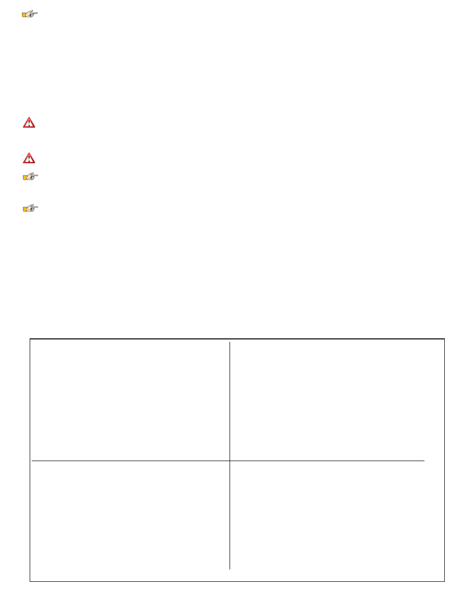
Traditional Models with Single Aileron Servo
Model Control Type setting: Standard (this is the default)
Guardian Receiver Inputs
o
Receiver Aileron Output → Guardian Aileron In
o
Receiver Elevator Output → Guardian Elevator In
o
Receiver Rudder Output → Guardian Rudder In
o
Guardian Aux-In is not connected
Guardian Servo Outputs
o
Guardian Aileron Out → Aileron Servo (if no Aileron
present, connect Rudder Servo to Aileron Out)
o
Guardian Elevator Out → Elevator Servo
o
Guardian Rudder Out → Rudder Servo
o
Guardian Aux Out is not connected
Traditional Models with Dual Aileron/ Flaperon servos (with
Transmitter mixing)
Model Control Type setting: Standard (this is the default)
Guardian Receiver Inputs
o
Receiver Aileron Output → Guardian Aileron In
o
Receiver Elevator Output → Guardian Elevator In
o
Receiver Rudder Output → Guardian Rudder In
o
Receiver Second Aileron or Flaperon Output → Guardian
Aux In
Guardian Servo Outputs
o
Guardian Aileron Out → Aileron Servo
o
Guardian Elevator Out → Elevator Servo
o
Guardian Rudder Out → Rudder Servo
o
Guardian Aux Out → Second Aileron or Flaperon Servo
V-Tail with Ailerons
Model Control Type setting: V-Tail
Guardian Receiver Inputs
o
Receiver Aileron Output → Guardian Aileron In
o
Receiver Elevator Output → Guardian Elevator In
o
Receiver Rudder Output → Guardian Rudder In
o
Receiver Second Aileron Output → Guardian Aux In
(optional)
Output
o
Guardian Aileron Out → Aileron Servo
o
Guardian Elevator Out → V-Tail Servo 1
o
Guardian Rudder Out → V-Tail Servo 2
o
Guardian Aux Out → Second Aileron Servo (optional)
Elevon / V-Tail with no Ailerons
Model Control Type setting: Elevon
Guardian Receiver Inputs
o
Receiver Aileron Output → Guardian Aileron In
o
Receiver Elevator Output → Guardian Elevator In
o
Receiver Rudder Output → Guardian Rudder In
o
Guardian Aux-In is not connected
Output
o
Guardian Aileron Out → Elevon Servo 1
o
Guardian Elevator Out → Elevon Servo 2
o
Guardian Rudder Out → Rudder Servo
o
Guardian Aux Out is not connected
Figure 4: Receiver and Servo Connections for Typical Wing Types
The current pitch and roll are recorded every time the Mode switch is transitioned out of a 2D-Mode position at the beginning of a toggle gesture. Once the 5-toggle
gesture is completed, those recorded pitch and roll values are stored to permanent memory as the new level flight orientation. If the 5-toggle gesture does not complete
within the standard time-out (1 second per toggle), then the recorded orientation information is discarded and no changes are made.
Receiver Requirements
Receiver Connection Requirements
The number of connections between the Guardian and your receiver depends on type and capabilities of your model, the level of Guardian in-flight control you require, and
the number of spare receiver channels you have. For very basic models, the Guardian is capable of operating with only the Elevator input and Aileron input connected.
BEC/Receiver Battery Power Requirements
The Guardian 2D/3D Stabilizer is sensitive to deep voltage drops, which means that your BEC or receiver battery must be sufficient to maintain a voltage of at least
3.5 volts, even under full servo load. The Guardian will shut off if the voltage drops below this level! Under normal conditions, the BEC voltage should
be at least 4.5 volts to achieve the best stabilization performance. Never exceed 16V!
If the voltage drops below 3.5 volts for a short period of time, the Guardian will experience a “brownout.” In this case, the Guardian will attempt to recover gracefully.
During recovery, stabilization may be disabled or suffer from performance issues while it does so.
If you experience issues like this in flight, bring the Mode/Config Switch to either 3D Mode or Stabilization Disabled Mode (if your transmitter is
configured for mode control) and land immediately.
If a brownout condition is detected by the Guardian, the LED will blink an error code of four long blinks followed by one short blink. If this LED signal is ever
seen after a flight, it is recommended that the BEC or battery be upgraded. Please see the Status LED section for more information on how to interpret LED blinks.
Failsafe position of Receiver Inputs
If, after you reset level flight and trims, an input channel should become disconnected from your receiver during flight, it will cause the Guardian to use the stored
trim setting for that servo channel input as a failsafe.
Functionality Limitations without the Mode and Gain Inputs or the PC Connection
While the Guardian is capable of flying without the Mode or Gain inputs being connected, most configuration steps need either the Mode input or a PC connection in order
to be done correctly. The Guardian comes preconfigured for standard fixed wing flight. Configuring the Guardian any other way will need to be set up using either the
Radio Stick Menu, which is activated using the Mode switch, or the PC Software, which requires a USB connection. Either the Mode Input or a PC is needed to Reset Level
Flight and Trims as well.
In the case where neither of these is available, it is recommended that you remap an unused channel, such as Throttle or Rudder to the Mode Input temporarily to emulate a
Mode Switch. Next, ensuring that your controller’s servo ranges for that channel are set to 100%, the remapped channel can be used to enter the Radio Stick Menu.
While the Radio Stick Menu will allow most configurations, it is only possible to access some features through the PC Software. These include the AHI display, saving and
reloading past configurations and the ability to limit your Servo Deflections (available under the Servo Config tab).
Wing Type Configuration
The Guardian is configurable for most common wing types. By default, it is configured for traditional wing control. Please refer to Figure 4, which shows the receiver and
servo connections for typical wing types.