The receiver connection harness 4, Configuring the mode and gain channels 4, The receiver connection harness – Eagle Tree Guardian 2D/3D Stabilizer User Manual
Page 4: Configuring the mode and gain channels
Copyright 2013-2014 Eagle Tree Systems, LLC Page 4
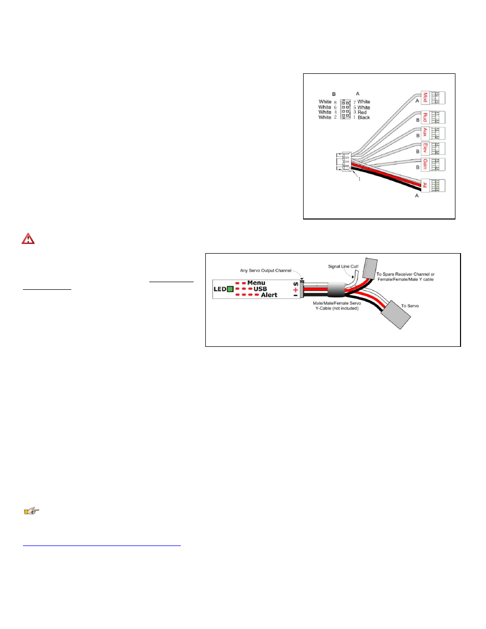
Figure 2 – Receiver Connection Harness
Figure 3 – Providing Backup Power when all Guardian Servo Channels Used
The Receiver Connection Harness
Receiver Connection Harness Pinout
The lightweight receiver connection harness with labeled connectors should make it easy for you to hook
up the Guardian to your receiver.
A diagram of the harness is shown in Figure 2, for your reference. It has the following labeled receiver
connections:
Ail – (required) Connects to your receiver’s Aileron output channel. Note that this channel also
supplies power and ground to the Guardian and the servos connected to the Guardian.
Elv – (required) Connects to your receiver’s Elevator output channel
Rud – (optional) Connects to your receiver’s Rudder output channel
Aux - (optional) Connects to your receiver’s Second Aileron or Flaperon output channel, if needed
Mod – (optional, recommended) The Mode/Config input connects to either a two-position or three-
position switch. It allows you to switch the Guardian mode during flight and to do radio stick
configuration of the Guardian. See the Mode/Config Switch Behavior section for more information.
Gain – (optional) The Gain input connects to a knob (or slider) on your receiver, and lets you adjust
the overall stabilizer gain during flight. See the Stabilization “Master Gain” Control section for more
information.
Receiver Connection Harness Load Capacity
When connected typically, the Aileron lead of the Guardian’s receiver connection harness takes power
from your receiver, and this powers the servos you have connected to the Guardian. The Receiver
Connection Harness is easily capable of handling the power requirements of typical analog and digital
servos.
However, if the servos you have connected to the Guardian are very large, and/or have a combined current draw of greater than 5 amps, an additional
power cable is required. Note that if your BEC or receiver battery is rated at 5 amps or less (the vast majority are), a backup cable should not be needed. Note
also that the Aileron lead of the harness should not be excessively
warm after flying, which could indicate that backup power is
needed.
If the servos you have connected to the Guardian draw greater than
5 amps all together, there are two ways to supply additional power
to your servos, which will provide additional current carrying
capability to the servos you have connected to the Guardian:
1)
If you are not using all the servo output connections on your
Guardian, a male to male servo wire (with the signal line cut!)
can be connected between a free servo channel on the
Guardian, and a free channel on your receiver.
2)
If all the servo connections on the Guardian are being used, a
male/male/female Y cable (ET p/n CAB-Y-1 or similar) with
the signal line cut can be used to provide additional power to the servos, as shown in Figure 3.
Configuring the Mode and Gain Channels
For best results, we recommend that the Mode/Config input wire (labeled Mod) on the receiver connection harness be connected to a channel on your receiver that is
controlled by a 2 or 3 position switch. If you have problems getting this to work, you can test the switch temporarily by connecting a servo to the channel on your receiver
that is controlled by it. Then, move the switch. If it has 2 positions, you should see the servo move from one extent to the other. If it has 3 positions, you should see the servo
move from one extent, to center, and to the other extent.
Once you confirm this, reconnect your Mod wire to that channel. If using a 2 position switch, the Guardian will then be able to be switched between 2D and 3D Mode. If
using a 3 position switch, the Guardian will be able to be switched between 2D, off, and 3D. If you want to use the Guardian with a 2 position for 2D and off, you will need
to reduce one endpoint for that channel (if your transmitter is capable of adjusting endpoints) so that in one position the Guardian's LED blinks, and in the other position it
stays off.
If you have an additional free channel that can be controlled by a slider or knob, you can use this channel to remotely change the Overall Gain on the Guardian, by
connecting that channel to the Gain wire on the receiver connection harness. In order to test this slider or knob, temporarily connect a servo to the channel on your receiver
that is controlled by the knob/slider. Then, move the knob/slider. You should see the servo move from one extent to the other as you operate the knob/slider.
Performing Reset Level Flight and Trims
Assuming you are using a Mode switch, you will want to power the system on with the switch in the 2D or 3D Mode position. Then, within 15 seconds of powering on the
system, move the switch to the opposite position and back to the original position quickly. The control surfaces will twitch once to indicate level flight and trims has been
set.
The meaning of each switch position can be custom defined through the PC software. See The Mode Config Tab in the The Guardian Configuration Page Software
Reference section of this manual, for more information.
If you need more detailed information about programming your specific radio, it is suggested to refer to your radios operating manual. Otherwise, you may want to check
the Guardian thread on rcgroups.com to see if someone else is using the same setup you are. The thread is located here;
Performing Reset Level Flight in the Air
Sometimes, the most accurate way to record level flight is when your model is in the air, flying straight and level. Fifteen seconds after initial power-on, the Guardian will
enable a 5-toggle gesture that will record the current pitch and roll before storing it as the new level flight orientation.
The recommended method to best utilize this feature is to enable 2D Heading Hold. Given a little time to settle out, the 2D Heading Hold should make the model fly very
straight, allowing you to focus on just controlling altitude with the Elevator stick. Once the model is flying straight and level, perform the 5-toggle gesture. Upon
completion, the orientation that the model was in at the beginning of the toggle gesture will be used as the new level flight orientation.