Tuning stabilization gains 7 – Eagle Tree Guardian 2D/3D Stabilizer User Manual
Page 7
Copyright 2013-2014 Eagle Tree Systems, LLC Page 7
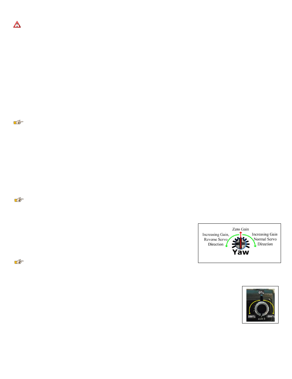
Figure 7 – Guardian Gain Control Dials
ground with little or no input, then your configuration is correct. If the model oscillates or overcompensates during the hand-toss, your Gain is too high.
Once it has been shown that the Guardian has been correctly configured, perform a run-up on the ground with stabilization enabled, while watching your control surfaces for
drift. If it appears as if stabilization is working properly with the engine active, then throttle down, perform one last preflight check and take off with power.
Don’t fly your model if your control surfaces are moving unexpectedly during engine run-up!
Once in the air and only when safe, release the control stick so it sits at zero deflection with 2D Mode enabled. Your airplane should fly straight and level. If not, your
Guardian may be mounted improperly or you need to re-trim your airframe. Disable stabilization by flipping the Mode/Config switch to the center position (if available).
Trim your controller in this mode until the plane achieves level flight. Land and follow the instructions for “Resetting Trims” on the ground.
Tuning Stabilization Gains
Stabilization Theory
The Guardian 2D/3D Stabilizer uses accelerometers and gyroscopes to measure the orientation of your model relative to the local direction of Earth’s gravity. In addition, it
interprets Pitch and Roll attitudes commanded by your Elevator and Aileron stick movements, respectively.
With this information, it is able to determine the error between your requested flight attitude and your plane’s true orientation. By passing this error through a controller
algorithm and sending it as servo commands through its Elevator, Aileron and Rudder outputs, the Guardian can help turn your squirrely model into a smooth-flying wing
on rails!
Each axis has a separate gain control dial, which is used to adjust gain on that axis. The Pitch, Roll and Yaw gains are then scaled by the optional Overall “Master Gain”
control, which can be mapped to a knob (or slider) on your transmitter. This arrangement allows individual axis gain adjustment while also providing in-flight Overall Gain
adjustment to compensate for varying conditions and aerodynamic performance.
In general, the higher the gain, the more responsive and resilient your plane will be to disturbances such as wind, balance and trim issues. Tuning the gains too high
however may result in oscillations of the airframe. It is recommended that the Master Gain control be used to tune the airframe until it barely oscillates and then be turned
back down. This will ensure the best performance while preventing future oscillations.
Since the Guardian interprets your radio’s control stick inputs as commanded Pitch/Roll angles or angular rates, it is common for the servos’ movements to be
exaggerated when you move the control stick at high gains. This is normal. In the air, the plane should perform as expected. See Preventing Damage to Your Model for
information on limiting servo throws with the Guardian.
Components of Stabilization
The Guardian employs two major techniques to stabilize your model: “rate stabilization and “orientation stabilization”. Sometimes called “derivative” and “proportional”
stabilization respectively, these two behaviors work together to smooth out bumps in the air while keeping your model in the orientation you want it.
Rate Stabilization
This is the reaction of the model to instantaneous motion. Specifically, it is the movement of your servos to oppose the angular rate of your model. The faster your model
is rotating in a given direction, the harder the Guardian will oppose that motion. This is the effect that smoothes turbulence and makes your model feel more stable. In
addition, when you fly in 3D Mode with 3D Heading Hold disabled, this is the only type of stabilization used.
Orientation Stabilization
This is the reaction of the model to the error between its current orientation and its commanded orientation. For instance, in 2D Mode with the sticks centered, the further
the model is brought from level orientation, the harder the Guardian will fight to bring it back. This behavior is also used in 3D Mode when 3D Heading Hold is active to
keep the model pointed in its locked direction.
When in 3D Mode, Orientation Stabilization is used in the Pitch, Roll and Yaw axes to keep your model on track. When in 2D Mode, Orientation Stabilization is
only used on the Pitch and Roll axes, leaving the Yaw axis (Rudder) only with Rate Stabilization. This will make the Rudder appear to be stabilizing less than the Elevator
and Ailerons (or Elevons) in 2D Mode. This is expected behavior.
Individual Axis Gain Dials
The gain control dials on the Guardian can be used for tuning the individual axes on your airframe. In addition, they
allow for the reversal of the direction of stabilization servo travel. When a dial is centered (with the “double-dot”
dial indication facing upwards, as shown in Figure 7) the gain for that axis is set to zero. This effectively disables
stabilization on that axis.
When a dial is rotated away from its centered position in the clockwise direction, the gain for that axis is increased,
and the stabilization deflection direction is set to normal. If the dial is rotated counterclockwise from its centered
position, the gain will be increased as well, but the stabilization deflection direction will be reversed. This allows for
stabilization to be tuned for any airframe, regardless of servo orientations.
If you have difficulty seeing the double-dot indication on the dials, you can either gently rotate the dials
counterclockwise and clockwise to find the approximate center point, or you can use the PC software to visualize the dial settings on your computer screen.
Stabilization “Master Gain” Control
The Master Gain control increases or decreases the effective amplitude of the Pitch/Roll/Yaw gain dials and serves as a way to easily tune all three. If you have an RC
controller that has a free analog knob or slider, this can be mapped to the Gain channel to allow for overall in-flight stabilization gain adjustment.
The higher the gain knob setting, the stronger the Guardian’s stabilization effect will be.
Another way to think about this is that it is similar to a graphic equalizer and volume control on a stereo. The individual gains are similar to the
sliders on the equalizer, while the Master Gain is similar to the overall volume control.
Though not required, ideally the Gain wire from the Guardian will be plugged into a channel controlled by a knob, slider or switch on the
transmitter. If you do not have a knob or slider on your transmitter than can be used for the Master Gain function, you may use a two or three
position switch to provide low/high or low/mid/high gains by adjusting the travel limits in your transmitter. If you have no available channel for
the Gain wire, you may leave it disconnected. In this case, the gain range of the individual gain dials is reduced to slightly less than half of the maximum possible gain to
reduce the possibility of encountering oscillation. See the figure 7A below.
Setting the Pitch/Roll/Yaw gain dials on the Guardian and the Master Gain control on the transmitter at maximum provides maximum stabilization.