Warning – Dunkirk Helix VX Vertical Laser Tube Wall Hung Stainless Steel Modulating Condensing Boiler User Manual
Page 83
83
OPTIONAL USER INTERFACE RELOCATION
User interface can be easily relocated outside of the boiler.
1.
Follow instructions TO TURN OFF GAS TO APPLIANCE
found on page 42. Verify all electrical power to boiler is
turned off.
WARNING
Electrical shock hazard. Turn OFF electrical power supply at
service panel.
!
2.
Remove front jacket panel.
WARNING
Burn hazard. Verify heat exchanger, igniter, and flame
sensor have cooled or use appropriate personal protection
equipment before removing.
!
3.
Inspect combustion chamber through sight glass.
Verify flame is not present. See figure 11.1 page 43.
4.
Disconnect the two position Molex connector between
main boiler harness and user interface. See figure A.
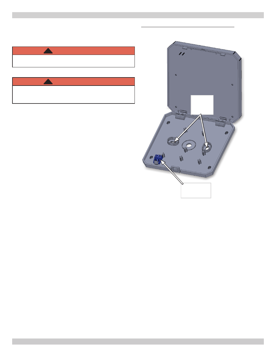
5.
Use small screwdriver to push in the plastic clip on
bottom of user interface. Pull outward on bottom of
user interface to release it from it base.
6.
Use small flat blade screwdriver to disconnect the two
wire harness from the terminal block located in user
interface base. Disconnect other end of harness at 2
pin connector. Secure unused connector to harness
bundle with wire tie. This harness will not be required
when mounting user interface outside of boiler.
7.
Before installing user interface in new location, route
new two conductor wire through hole in back of user
interface base. Connect the wires to terminal block.
This connection is not polarity sensitive.
8.
Install user interface base in new location using
appropriate field sourced screws.
9.
Install user interface on the base by engaging upper
tabs on rear into user interface base slots. With
downward hinging motion lower the display until user
interface snaps onto the base. Verify two pins on back
of user interface are properly aligned with the holes in
user interface base terminal block as user interface is
installed.
10.
Route other end of new two conductor wire through low
voltage knockout on boiler.
11.
Connect two conductor wire to low voltage terminal
block terminals labeled user interface. This connection
is not polarity sensitive.
12.
Replace front jacket panel.
13.
Apply power and verify proper operation of the display
following instructions in Appendix A - Control Module.
14.
Verify proper boiler operation by following START UP
PROCEDURE located in this manual.
Figure - A User Interface Terminal Block
Terminal
Block
Base
Screw
Location