Warning – Dunkirk Helix VX Vertical Laser Tube Wall Hung Stainless Steel Modulating Condensing Boiler User Manual
Page 14
14
• Individual boiler discharge piping shall be independent
of other discharge piping.
• Size and arrange discharge piping to avoid reducing
safety relief valve relieving capacity below minimum
relief valve capacity stated on rating plate.
• Run pipe as short and straight as possible to location
protecting user from scalding and properly drain
piping.
• Install union, if used, close to safety relief valve outlet.
• Install elbow(s), if used, close to safety relief valve
outlet and downstream of union (if used).
• Terminate pipe with plain end (not threaded).
• Arrange piping to prevent water dripping onto boiler.
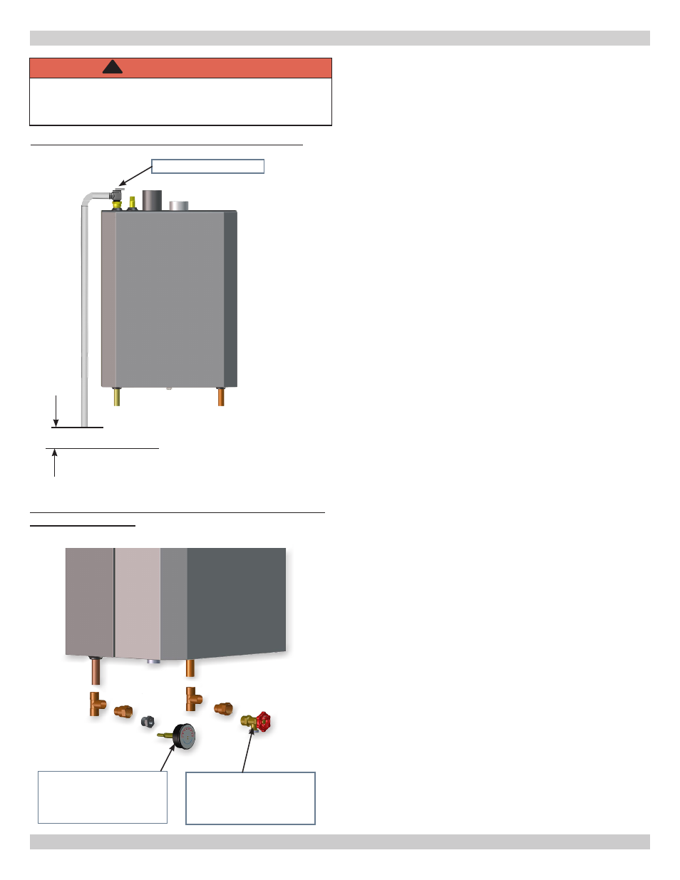
5.4 Trim Piping
• Temperature - Pressure Gauge. Install temperature
pressure gauge using adapter, tee and bushing provided
with boiler. See figure 5-3.
• Protect chassis grommets from heat damage while
soldering.
• Drain Valve. Install drain valve using, tee and adapter
provided with boiler. See figure 5-3.
5.5 System Piping
• See Table 3 for basic system piping configurations.
• Systems with automatic fill valves require back flow
prevention device.
• Single boiler system. See figures 5-4A, 5-5, 5-6, 5-7A & B
for general guidance. Additional considerations:
• Boiler control is designed for single central heating
pump. Installer responsible for integration of
multiple central heating pumps.
• Boiler control allows domestic hot water
prioritization. Function could be lost if central
heating pump not directly connected to control
system.
• Multiple boiler system. See figures 5-8A, B & C for
general guidance. Additional considerations:
• Control system requires equivalent water
temperatures entering each boiler to properly
sequence and adjust system supply temperature.
• Install multi boiler sensor kit. See "Parts, Kits &
Optional Accessories" manual for part number.
• Low Water Cutoff (LWCO) probe location. See figures
5-4A for minimum probe height. Do not install shutoff
valve between boiler and LWCO probe.
• If boiler is below radiation level, use figure 5-4A.
Boilers above radiation level use figures 5.4B thru
5.4D.
• If using separate stand pipe, install air vent using
tee to avoid nuissance shutdowns.
• See figures 5-4B, 5-4C and 5-4D for suggested
probe location alternatives.
• Arrange piping to prevent water dripping onto boiler.
FIGURE 5-3 Temperature Pressure Gauge and Drain
Valve Installations
Temperature Pressure
Gauge shown at
System Supply
Connection
Check Local Codes
For Maximum
Distance To Floor
WARNING
Burn and scald hazard. Safety relief valve could
discharge steam or hot water during operation.
Install discharge piping per these instructions.
!
FIGURE 5-2 Safety Relief Valve Discharge Piping
Drain Valve shown
at System Return
Connection to Boiler
Safety Relief Valve
5 - HYDRONIC PIPING