Notice – Dunkirk Helix VX Vertical Laser Tube Wall Hung Stainless Steel Modulating Condensing Boiler User Manual
Page 35
35
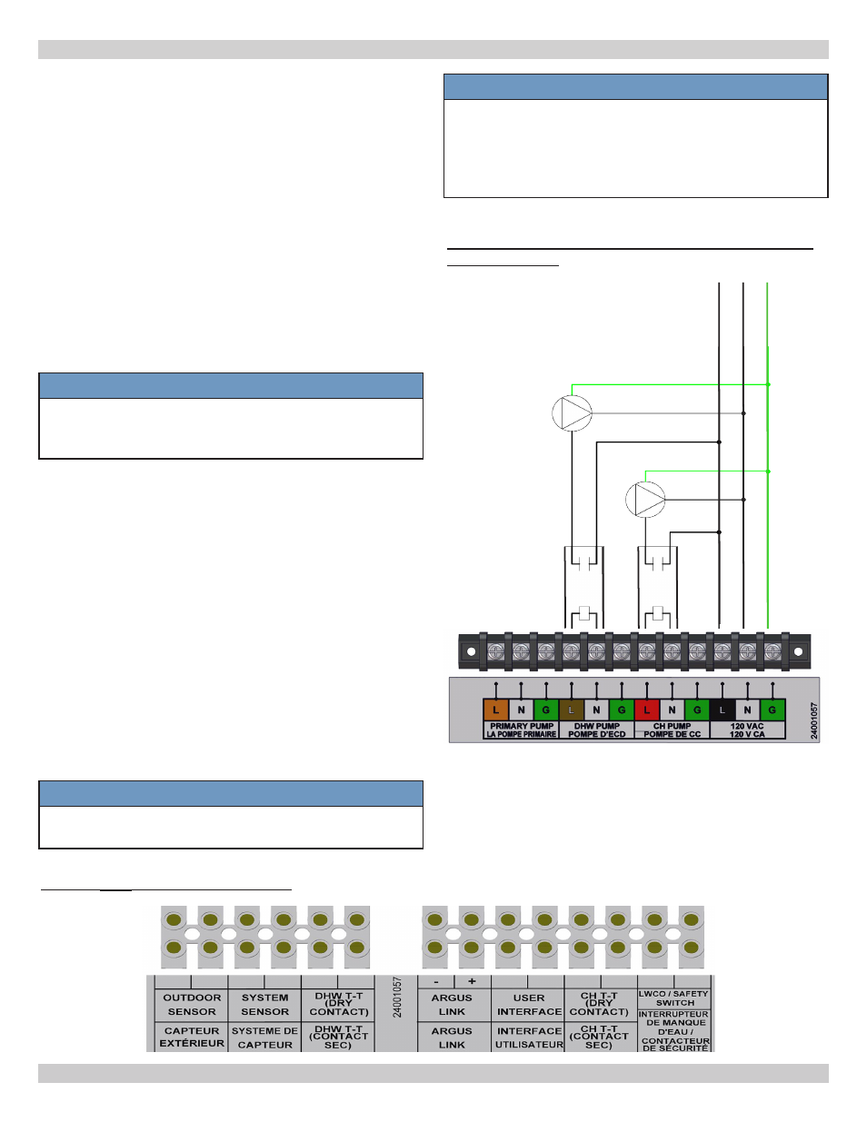
• Argus Link (Multiple boiler applications only)
• Outdoor Sensor, if used.
A. Provided with boiler.
B. Locate outdoor sensor to protect against wind and
direct sunlight. Mounting instructions provided with
sensor.
C. Maximum wire length is 100 ft (30m) for 22 ga.
wire, or 150 ft (45m) for 18 ga. wire.
D. Connect wires to OUTDOOR SENSOR terminals.
Wires are interchangeable.
• System Sensor (Multiple boiler applications only)
• Domestic Hot Water (DHW) Thermostat, if used.
A. Use temperature control with dry contacts rated
at 0.5 amps @ 120 VAC. Boiler control does not
provide power to DHW temperature control.
NOTICE
IMPORTANT: Do not apply power to DHW T-T
terminals. Dry contact only, use of isolation relay
may be necessary.
B. Maximum wire length is 330 ft (100m) 22 gauge wire.
C. Connect wires (interchangeable) to DHW T-T
terminals. Wires are interchangeable.
• Central Heating Thermostat
A. Use thermostat or boiler system control with dry
contacts related 0.5 amps @ 120 VAC.
Boiler control
does not provide 24 VAC power to central heating
thermostat.
B. Locate and install thermostat per manufacturer's
instructions. Maximum wire length is
330 ft (100m) for
22 ga. wire.
C. Connect wires to CH T-T terminals. Wires are
interchangeable.
• Low Water Cutoff (LWCO)
Connect LWCO switch leads to terminals provided. See
Figures 14.1 thru 14.4 for wiring diagrams. Provide
power to LWCO per manufacturer's instructions.
NOTICE
Boiler transformer does not have adequate VA to
power accessories, including LWCO.
FIGURE
8-4
External Connections (Do not apply external voltage to external terminals.)
NOTICE
Use dry contact for wires to CH T-T terminal and
DHW T-T terminal. E33 error code is displayed if
voltage is sent back to the control board. If error
is not corrected for extended period of time, this
voltage can permanently damage control board.
8 - ELECTRICAL CONNECTIONS
FIGURE
8-3
Isolation Relays for CH System Pump
and DHW Pump
DHW
Pump
CH
Pump
Relay
120VAC
coil
DHW
Pump
Relay
120VAC
coil
CH
Pump