Digital i/o connector (cn1), Inverter connectors (cn5), Internal usb 2.0 connectors (cn10, cn12) – Axiomtek IPC932-230-FL-ECM User Manual
Page 17: 1 digital i/o connector (cn1), 2 inverter connectors (cn5)
IPC932-230-FL Series U
ser’s Manual
Introduction
9
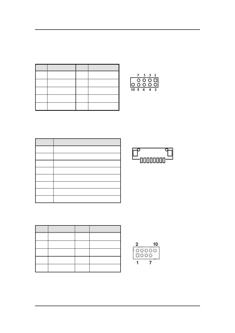
1.7.1 Digital I/O Connector (CN1)
The board is equipped with an 8-channel digital I/O connector that meets requirements for a
system customary automation control. The digital I/O can be configured to control cash
drawers and sense warning signals from an Uninterrupted Power System (UPS), or perform
store security control. You may use software programming to control these digital signals.
1.7.2 Inverter Connectors (CN5)
The CN5 is DF13-8P-1.25V 8-pin connector for inverter. We strongly recommend you to use
the matching DF13-8S-1.25C connector to avoid malfunction.
8 1
1.7.3 Internal USB 2.0 Connectors (CN10, CN12)
These are internal connectors for USB 2.0 interfaces.
CN12 (USB port 5 and 6)
CN10 (USB port 3 and 4)
Pin
Signal
Pin
Signal
1
DIO 1
2
DIO 8
3
DIO2
4
DIO 7
5
DIO 3
6
DIO 6
7
DIO 4
8
DIO 5
9
NC
10
GND
Pin
Signal
1
VBL1 (+12V level)
2
VBL1 (+12V level)
3
VBL2 (+5V level)
4
VBL_ENABLE
5
GND
6
GND
7
GND
8
LVDS_BRICTL
Pin
Signal
Pin
Signal
1
USB_PW R
2
USB_PW R
3
USB -
4
USB -
5
USB +
6
USB +
7
GND
8
GND
10
GND