Appendix b: interface specifications, Introduction, Serial – AMT Datasouth Fastmark 400 User Manual
Page 53
User's Guide 52
Appendix B: INTERFACE SPECIFICATIONS
Introduction
This appendix presents the interface specifications of I/O ports for the printer. These specifications
include pin assignments, protocols and detailed information about how to properly interface your
printer with your host or terminal.
Serial
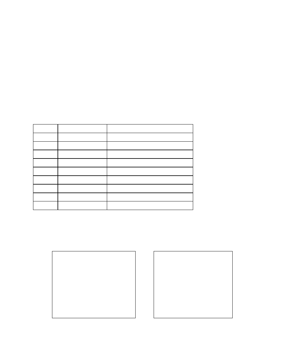
Pin Configuration
The RS-232 connector on the printer side is a female, DB-9.
Pin
Direction
Definition
1
Tied to in 6
Not used
2
In
Receive Data (RxData)
3
Out
Transmit Data (TxData)
4
-
No connection
5
-
Logic Ground
6
Tied to pin 1
Not used
7
Out
Request to Send (RTS)
8
In
Clear to Send (CTS)
9
Out
+5V
Note: Pin 9 is reserved for Keyboard Device Unit (KDU) only, do not connect this pin if you are
using a general host like a PC.
Connection with host:
Host 25S
Printer 9P
Host 9S
Printer 9P
(PC or compatible)
(PC or compatible)
DTR 20
----------- 1
DTR 4
----------- 1
DSR 6
----------- 6
DSR 6
----------- 6
TX 2
----------- 2 RX
TX 3
----------- 2 RX
RX 3
----------- 3 TX
RX 2
----------- 3 TX
CTS 5
----------- 7 RTS
CTS 8
----------- 7 RTS
RTS 4
----------- 8 CTR
RTS 7
----------- 8 CTS
GND 7
----------- 5 GND
GND 5
----------- 5 GND