Compactpci j5 pin assignment – ADLINK cPCI-6520 User Manual
Page 49
Board Interfaces
37
cPCI-6520
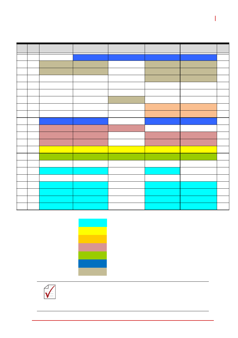
CompactPCI J5 Pin Assignment
Pin
Z
A
B
C
D
E
F
22
GND
Power LED
LAN2_LINK_ACT# LAN2_VCC_TERM LAN3_LINK_ACT# LAN3_VCC_TERM GND
21
GND
eDP_TX1+
eDP_TX1-
GND
eDP_TX3+
eDP_TX3-
GND
20
GND
eDP_TX0+
eDP_TX0-
GND
eDP_TX2+
eDP_TX2-
GND
19
GND
GND
GND
GND
eDP_AUX+
eDP_AUX-
GND
18
GND
NC
NC
GND
NC
NC
GND
17
GND
NC
NC
GND
NC
NC
GND
16
GND
GND
GND
eDP_HPD#
GND
GND
GND
15
GND
NC
NC
GND
SATA-RX5+
SATA-RX5-
GND
14
GND
NC
NC
GND
SATA-TX5+
SATA-TX5-
GND
13
GND
LAN2_100#
LAN3_100#
NC
LAN3_1G#
LAN2_1G#
GND
12
GND
DVI_DATA
DVI_CLK
DVI_HTPLG
NC
NC
GND
11
GND
TDC2+
TDC2-
GND
TLC+
TLC-
GND
10
GND
TDC0+
TDC0-
GND
TDC1+
TDC1-
GND
9
GND
GPIO1
GPIO2
GPIO3
GPIO4
GPIO5
GND
8
GND USB3.0_SSTX3+ USB3.0_SSTX3-
GND
USB3.0_SSRX3+ USB3.0_SSRX3- GND
7
GND
GND
GND
RTC
GND
GND
GND
6
GND
PCIE-CLK+
PCIE-CLK-
GND
RESET#
SATA_LED
GND
5
GND
GND
GND
GND
GND
GND
GND
4
GND
PCIE-TX3+
PCIE-TX3-
GND
PCIE-RX3+
PCIE-RX3-
GND
3
GND
PCIE-TX2+
PCIE-TX2-
GND
PCIE-RX2+
PCIE-RX2-
GND
2
GND
PCIE-TX1+
PCIE-TX1-
GND
PCIE-RX1+
PCIE-RX1-
GND
1
GND
PCIE-TX0+
PCIE-TX0-
GND
PCIE-RX0+
PCIE-RX0-
GND
NOTE:
NOTE:
If one of the front panel DisplayPorts is converted to DVI or
HDMI, the cPCI-6520 can support only two independent dis-
plays via the front panel and the rear I/O display output is dis-
abled.
PCI Express x4
GPIO
Serial ATA
DVI
USB 3.0 ports
Ethernet ports
eDP