Vout vref dan = − × 4096, 2 d/a conversion – ADLINK ACL-8111 User Manual
Page 36
30
• Operation Theorem
4.2 D/A
Conversion
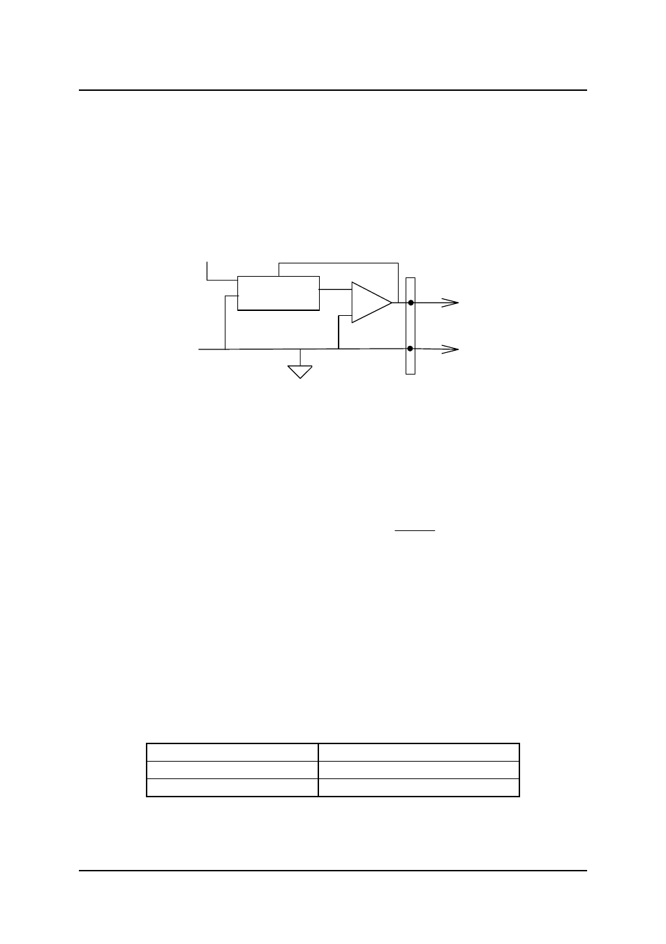
The operation of D/A conversion is simpler than A/D operation. You only
need to write digital values into the D/A data registers and the corresponding
voltage will be output from the AO. The ACL-8111 has one uni-polar analog
output channels. To make the D/A output connections from the appropriate
D/A output, please refer Figure 4.2.
To D/A Output
D/A Converter
-
+
Ref In
-5 or -10
INT or Ext
Analog GND
Pin-30 ( AO)
Pin-20 ( A.GND)
Figure 4.2 Connection of Analog Output Connection
The mathematical relationship between the digital number DAn and the
output voltage is formulated as following:
Vout
Vref
DAn
= −
×
4096
Where the Vref is the reference voltage, the Vout is the output voltage, and
the DAn is the digital value in D/A data registers.
Before performing the D/A conversion, users should care about the D/A
reference voltage, which set by the JP1. Please refer section 2.6 for jumper
setting. The reference voltage will effect the output voltage. If the reference
voltage is -5V, the D/A output scaling will be 0~5V. If the reference voltage is
-10V, the D/A output scaling will be 0~10V. The relationship of reference
voltage and output range is summary in the following table.
Reference Voltage
DA Output Voltage Range
-5 V
0V ~ +5V
-10 V
0V ~ +10V