ADLINK ACL-8111 User Manual
Page 34
28
• Operation Theorem
Timer Pacer Trigger
An on-board timer / counter chip 8253 provide a pacer trigger source at a
fixed rate. Two counters of the 8253 chip are cascaded together to generate
trigger pulse with precise frequency. It's recommend to use this mode if your
applications need a fixed and precise A/D sampling rate. It can be combined
with the EOC (end-of-conversion) interrupt data transfer.
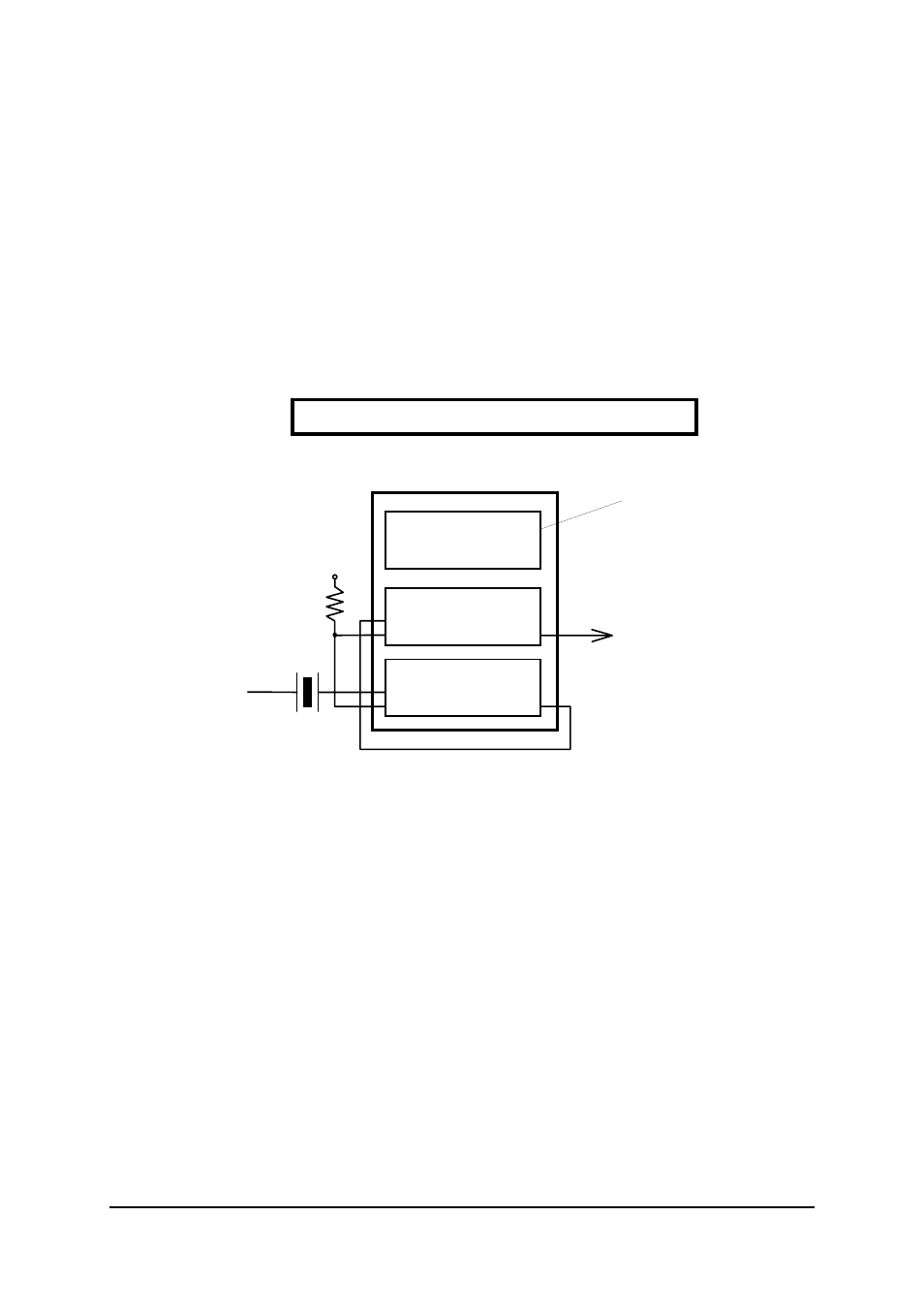
On the ACL-8111, the 8253 chip for timer pacer trigger source is configured
as below:
The pacer rate of above configuration is determined by the formula:
Pacer rate = 2 MHz / (C1 * C2)
Counter 0
Counter 1
Counter 2
CLK0
GATE0
OUT0
CLK1
GATE1
CLK2
GATE2
OUT1
OUT2
2MHz
Oscillator
Vcc
Timer Pacer
8253 Timer/Counter
Not Used
The maximum pacer signal rate is 2MHz/4=500K, which excess the
maximum A/D conversion rate of the ACL-8111. The minimum signal rate is
2MHz/65535/65535, which is a very slow frequency that user may never use
it.
For example, if you wish to get a pacer rate 2.5 kHz, you can set C1 = 40 and
C2 = 10. That is
2.5KHz = 2Mhz / (40 x 20)
External Trigger
Through the pin-1 of CN2 (DI0), the A/D conversion also can be performed
when a rising edge of external signal is occurred. The conversion rate of this
mode is more flexible than the previous two modes, because the users can
handle the external signal by outside device. The external trigger can
combine with the interrupt data transfer, or even program polling data
transfer. Generally, the interrupt data transfer is often used when external
trigger mode is used.