2 vr assignment, 3 d/a adjustment – ADLINK ACL-8112 Series User Manual
Page 58
50
• Calibration & Utilities
6.2
VR Assignment
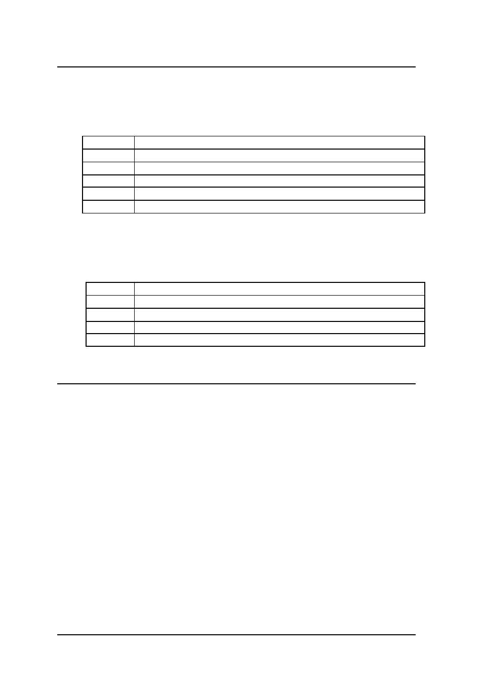
There are 6 variable resistors (VR) on the ACL-8112DG/HG board. These
allow you to make adjustment to the A/D and D/A channels. The function of
each VR is specified as Table 6.1 -1.
VR1
A/D full scale adjustment
VR2
A/D bipolar offset adjustment
VR3
D/A channel 1 full scale adjustment
VR4
D/A channel 2 full scale adjustment
VR5
A/D programmable amplifier offset adjustment
VR6
A/D unipolar offset adjustment
Table 6.1-1 Function of VRs in ACL-8112DG/HG
There are five variable resistors (VR) on the ACL-8112PG board. These
allow you to make adjustment to the A/D and D/A channels. The function of
each VR is specified as Table 6.1 -2.
VR1
A/D full scale adjustment
VR2
A/D offset adjustment
VR3
D/A channel 1 full scale adjustment
VR4
D/A channel 2 full scale adjustment
VR5
A/D programmable amplifier offset adjustment
Table 6.1-2 Function of VRs in ACL-8112PG
6.3
D/A Adjustment
6.3.1 D/A CH1 calibration
1. Connect the DVM <+> to CN3.AO1
CN3.GND
2. Write a digital value into the D/A register (BASE+4 and BASE+5).
3. Trim VR3 until +5 V appears on the DVM.