ADLINK ACL-8112 Series User Manual
Page 22
14
• Installation
I/O port
Address(Hex)
A9
1
A8
2
A7
3
A6
4
A5
5
A4
200-20F
--
(1)
ON
(0)
ON
(0)
ON
(0)
ON
(0)
ON
(0)
210-21F
--
(1)
ON
(0)
ON
(0)
ON
(0)
ON
(0)
OFF
(1)
220-22F
(default)
--
(1)
ON
(0)
ON
(0)
ON
(0)
OFF
(1)
ON
(0)
230-23F
--
(1)
ON
(0)
ON
(0)
ON
(0)
OFF
(1)
OFF
(1)
:
300-30F
--
(1)
OFF
(1)
ON
(0)
ON
(0)
ON
(0)
ON
(0)
:
3F0-3FF
--
(1)
OFF
(1)
OFF
(1)
OFF
(1)
OFF
(1)
OFF
(1)
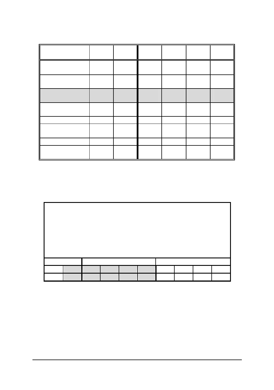
Table 2.2 Possible Base Address Combinations
A0, ..., A9 corresponds to the PC Bus address lines
A9 is fixed at “1”.
How to define/determine the base address of the ACL-8112 ?
DIP1 to DIP5 of SW1 corresponds to the PC bus address line A8 to
A4 respectively. A9 is always 1 and A0~A3 are always 0. If you want
to change the base address, you can only change th e values of A8 to
A4 (the shadow area of the table below). The following table is an
example, of how to set a base address of Hex 220
Base Address: Hex 220
2
2
0
1
0
0
0
1
0
0
0
0
0
A9
A8
A7
A6
A5
A4
A3
A2
A1
A0