2 analog input signal connection – ADLINK ACL-8112 Series User Manual
Page 33
Signal Connections
• 25
3.2
Analog Input Signal Connection
The ACL-8112 provides 16 single-ended or 8 differential analog input
channels. The analog signal can be converted to digital value by the A/D
converter. To avoid ground loops and obtain a more accurate measurement
of the A/D conversion, it is quite important to understand the signal source
type and how to choose the correct analog input mode: signal-ended or
differential. The ACL-8112 allows for the configuration through jumpers.
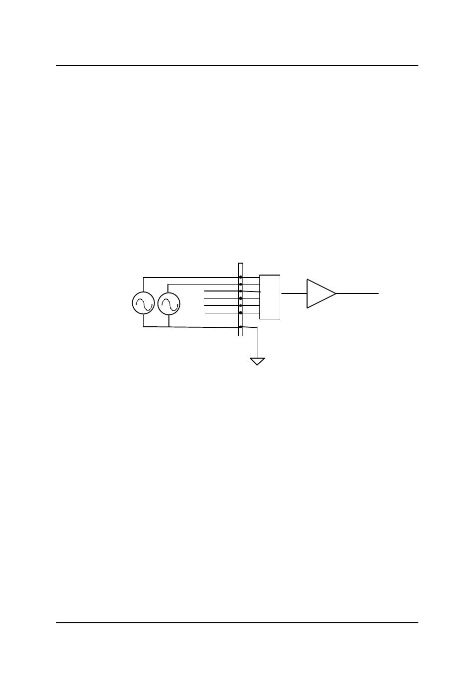
Single-ended Mode:
For single-ended mode, only one input is connected relative to ground and is
suitable for connecting with a floating signal source. Floating source means
it does not have any connection to ground. Figure 3.4 shows a single-ended
connection. Note that when two or more floating sources are connected, the
sources must be connected to common ground.
AIN
AGND
n = 0, ..., 15
Floating
Signal
Source
Opertiona
Amplifie
To A/D Converter
Input Multipexer
V1
V2
Figure 3.4 Floating source and single-ended
Differential input mode:
The differential input mode provides two inputs that respond to signal voltage
differences between them. If the signal source is ground-referenced, the
differential mode can be used to reduce ground loops. Figure 3.5 shows the
connection for differential input mode. However, even if the signal source is
locally grounded, the single-ended configuration can still be used when the
Vcm ( Common Mode Voltage) is very small and the effect of ground loop is
negligible .