12 a/d input range setting – ADLINK ACL-8112 Series User Manual
Page 28
20
• Installation
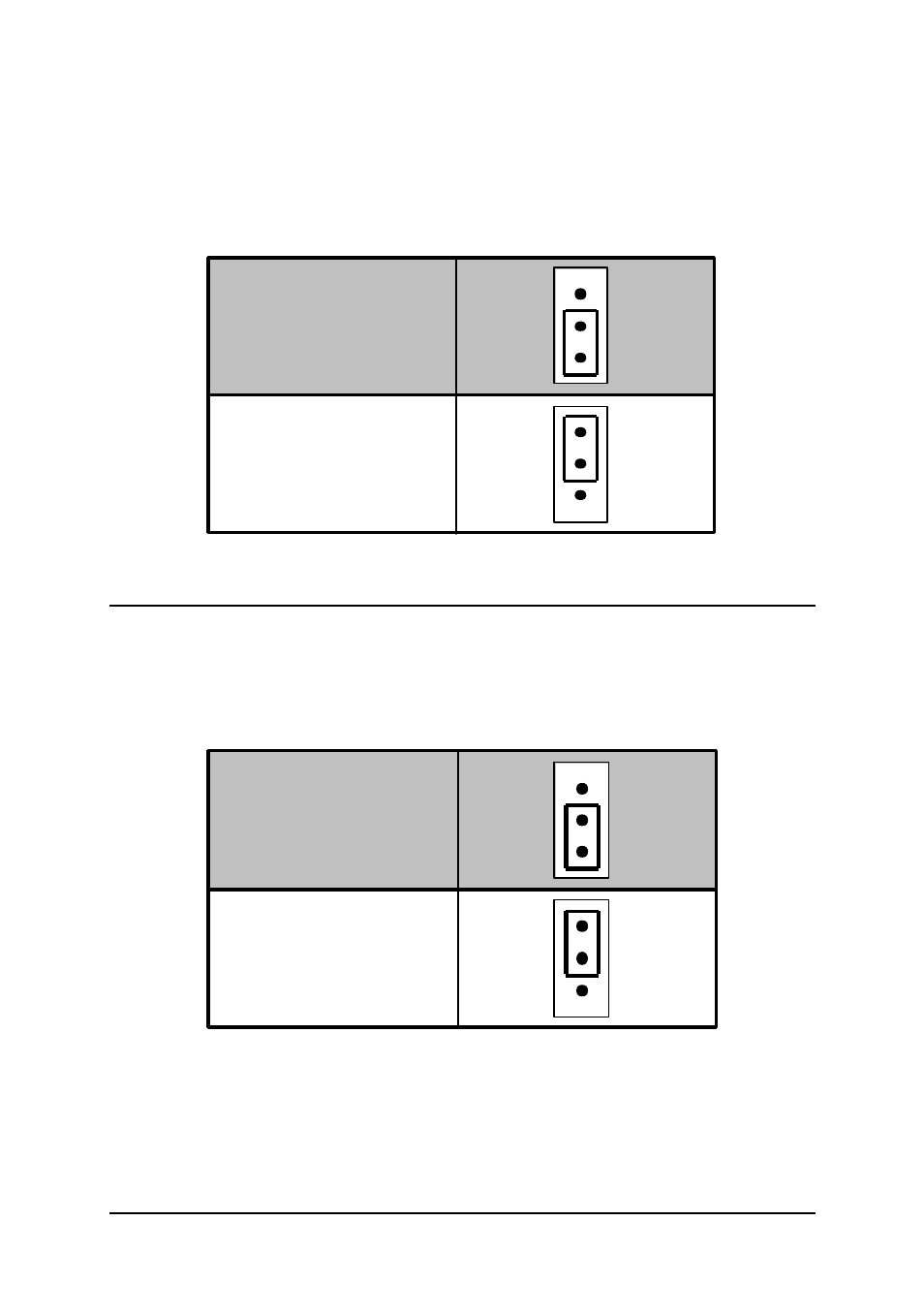
The internal voltage can be set to -5V or -10V which is selected by JP1 for
the ACL-8112DG/HG and JP8 for the ACL-8112PG. Possible configurations
are specified in Figure 2.9. Note that the internal reference voltage is used
only when JP2 of the ACL-8112DG/HG or JP6 and JP7 of the ACL-8112PG
is set to internal reference.
Reference Voltage is
-5V (default setting)
JP1 /
JP8
-10V
-5V
Reference Voltage is
-10V
JP1 /
JP8
-10V
-5V
Figure 2.9 Internal Reference Voltage Setting
2.12 A/D Input Range Setting
(This section is for the ACL-8112PG only)
The A/D input range of the ACL-8112PG can be set to
±
5V or
±
10V using
JP9.
A/D Input Range is +/-
5V (default setting)
JP9
10
5
JP9
10
5
A/D Input Range is +/-
10V
See also other documents in the category ADLINK Hardware:
- USB-1901 (84 pages)
- USB-1210 (54 pages)
- USB-2401 (60 pages)
- USB-7230 (50 pages)
- USB-2405 (56 pages)
- DAQe-2010 (92 pages)
- DAQe-2204 (100 pages)
- DAQe-2213 (94 pages)
- DAQe-2501 (74 pages)
- PXI-2010 (84 pages)
- PXI-2020 (60 pages)
- PXI-2501 (62 pages)
- cPCI-9116 (98 pages)
- ACL-8112 Series (93 pages)
- ACL-8112 Series (94 pages)
- ACL-8216 (75 pages)
- ACL-8111 (61 pages)
- PCM-9112+ (10 pages)
- PCM-9112+ (94 pages)
- cPCI-6216V (47 pages)
- ACL-6126 (28 pages)
- ACL-6128A (40 pages)
- PCM-6308V+ (52 pages)
- PCM-6308V+ (4 pages)
- PCI-7444 (82 pages)
- PCI-7434 (48 pages)
- PCI-7234 (56 pages)
- PCI-7260 (66 pages)
- PCI-7258 (38 pages)
- PCI-7256 (48 pages)
- PCI-7250 (48 pages)
- LPCI-7250 (48 pages)
- PCI-7396 (65 pages)
- PCI-7296 (59 pages)
- PCI-8554 (67 pages)
- PCIe-7360 (94 pages)
- PCIe-7350 (86 pages)
- PCIe-7300A (114 pages)
- PCIe-7200 (51 pages)
- PCI-7300A (112 pages)
- PCI-7300A (83 pages)
- PCI-7200 (96 pages)
- cPCI-7300 (82 pages)
- cPCI-7300 (83 pages)