4 a/d range control register – ADLINK ACL-8112 Series User Manual
Page 43
Registers
• 35
4.4
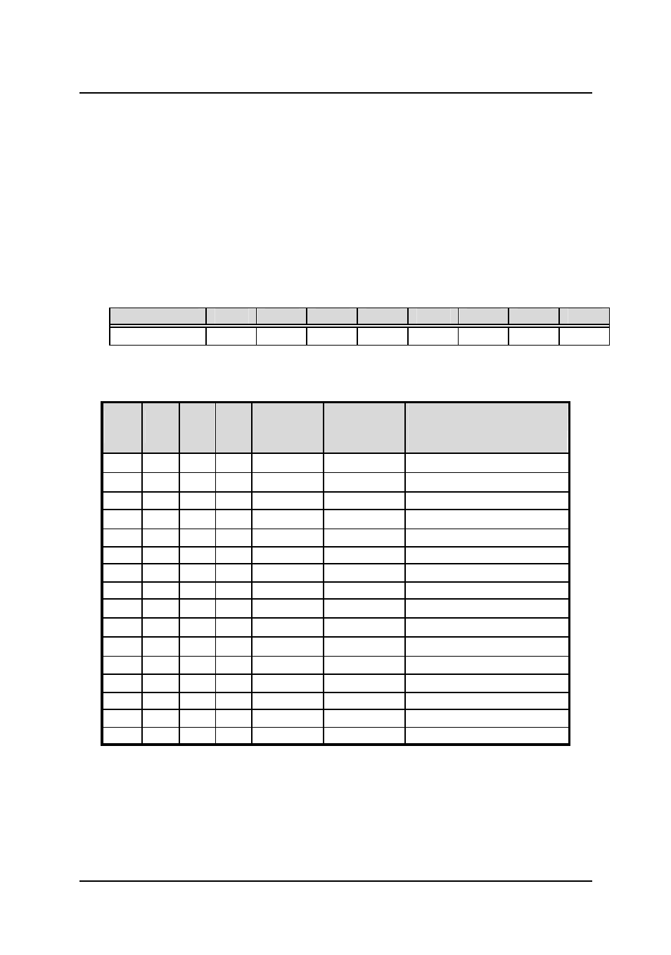
A/D Range Control Register
The A/D range register is used to adjust the analog input ranges for the
A/D channels. Two factor effects the input range: Gain and Polarity. For
the ACL-8112PG, This register controls the PGA (programmable gain)
directly and there is no Unipolar setting. When a different gain value is set,
the analog input range is changed. For the ACL-8112DG/HG, both the
PGA and polarity are controlled by this register. Table 4.2 shows the
relationship between the register data and the A/D input range.
Address : BASE + 9
Attribute: write only
Data Format:
Bit
7
6
5
4
3
2
1
0
BASE+9
X
X
X
X
G3
G2
G1
G0
G0~G3: Gain / Range selection, G3 is not used for ACL-8112PG
( This table is only for the ACL-8112HG: High Gain Card)
G3
G2
G1
G0
GAIN
Bipolar
or
Unipolar
Input Range
0
0
0
0
1
Bipolar
±
5V
0
0
0
1
10
Bipolar
±
0.5V
0
0
1
0
100
Bipolar
±
0.05V
0
0
1
1
1,000
Bipolar
±
0.005V
0
1
0
0
1
Unipolar
0V ~ 10V
0
1
0
1
10
Unipolar
0V ~ 1V
0
1
1
0
100
Unipolar
0V ~ 0.1V
0
1
1
1
1,000
Unipolar
0V ~ 0.01V
1
0
0
0
0.5
Bipolar
±
10V
1
0
0
1
5
Bipolar
±
1V
1
0
1
0
50
Bipolar
±
0.1V
1
0
1
1
500
Bipolar
±
0.01V
1
1
0
0
1
Unipolar
N/A
1
1
0
1
10
Unipolar
N/A
1
1
1
0
100
Unipolar
N/A
1
1
1
1
1,000
Unipolar
N/A
Table 4.2-1 Function of the Gain Control Bits