Daq timing signals, Table 4-8: user-controllable timing signals and, Functionalities – ADLINK DAQe-2006 User Manual
Page 81
Operation Theory
69
DAQ timing signals
The user-controllable internal timing-signals contain (refer to sec-
tion 4.1 for the internal timing signal definition):
1. TIMEBASE, providing TIMEBASE for all DAQ opera-
tions, which could be from internal 40 MHz oscillator,
EXTTIMEBASE from I/O connector or the
SSI_TIMEBASE. Note that the frequency range of the
EXTTIMEBASE is 1 MHz to 40 MHz, and the EXTTIME-
BASE should be TTL-compatible.
2. AD_TRIG, the trigger signal for the A/D operation, which
could come from external digital trigger, analog trigger,
internal software trigger, and SSI_AD_TRIG. Refer to
section 4.5 for detailed description.
3. SCAN_START, the signal to start a scan, which would
bring the following ADCONV signals for AD conversion,
and could come from the internal SI_counter, AFI[0] and
SSI_AD_START. This signal is synchronous to the
TIMEBASE. Note that the AFI[0] should be TTL-compat-
ible and the minimum pulse width should be the pulse
width of the TIMEBASE to guarantee correct functional-
ities.
4. ADCONV, the conversion signal to initiate a single con-
version, which could be derived from internal counter,
AFI[0] or SSI_ADCONV. Note that this signal is edge-
sensitive. When using AFI[0] as the external ADCONV
source, each rising edge of AFI[0] would bring an effec-
tive conversion signal. Also note that the AFI[0] signal
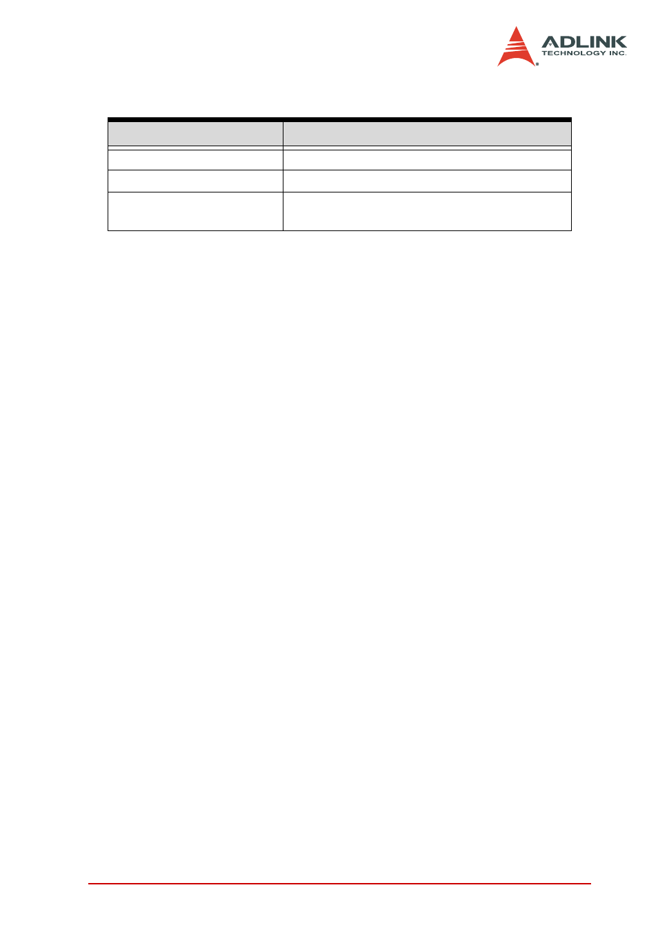
Timing signal category
Corresponding functionality
SSI/PXI signals
Multiple cards synchronization
AFI signals
Control DAQ-2000 by external timing signals
AI_Trig_Out,
AO_Trig_Out
Control external circuitry or boards
Table 4-8: User-controllable Timing Signals and Functionalities